

Introduction: ATTiny2313 Multi-mode LED Matrix Clock


this is a mutli-mode clock project based on attiny2313. it employs a 8x8 led matrix as display. with the limited resolution, this 12 hour clock shows time in 6 different modes.
the circuit employs row and column multiplexing to drive the leds, one row at a time, this gives a 12.5% duty cycle when "sets" of leds (8 of them in each of the 8 rows) are turn on briefly. current limiting resistors are eliminated to save breadboard estate and as we are not constantly driving individual leds, they are not going to be damaged.
the control (user interface) is also arranged so that we only use one tactile button for input. the firmware capture long button presses (press and hold) for menu rotation and normal button presses for menu selection.
this is a hobby project and the clock is only as accurate as your internal oscillator calibration. i had not use a crystal in this project as doing so will upset the "matrix on top of mcu" breadboard layout. a crystal can be used to increase accuracy on a alternate breadboard layout (or pcb). with software compensation, i can achieve may be within 2 minutes off a day. i would need to adjust the time every 3 or 4 days to keep it usable. this is more a cubicle talk piece than a swiss time piece.
Below is video on full construction
Step 1: Display Modes


hhmm mode (see attached image 1) , typical hours plus minutes scrolling digits with colon separator.
seconds mode, shows only seconds.
tix mode (see attached image 2), led matrix is divided into quadrant, the upper quadrants shows the hour in bcd (binary coded decimal) values. they are represented by the number of dots to indicate the digits. the lower quadrants show the minute in bcd. i.e. for 9:36 it shows no dot + 9 dots on the upper half and 3 dots + 6 dots on the lower half.
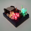
dice mode (see attached image 3), the led matrix is divided into two set of 'dices'. with the upper pair showing hour from 1 - 12, the lower pair of dice shows minutes in 5 minute increments. i.e. for 9:45 it shows dice value 9 (upper) + 9 (lower) (9 x 5 min).
binary mode (bcd, see attached image 4), the hour, minute and second digits are show as binary dot on different rows in the led matrix. the rows 0 and 1 (from top) represents the hour digits, rows 2 is blanked, row 3 and 4 represent the minute digits, row 5 is blanked, row 6 and 7 represents the second digits.
Step 2: Features and Parts

features
* minimal components, 3 parts
* battery operated from 3V to 5V
* use of watchdog timer to keep time, power-down sleep mode takes about 1uA power
* calibration allow setup of seconds to gain for each hour
* this is a 12H clock, not 24H and has no AM/PM indicator
* not very accurate, planning to add RTC chip
parts list
* attiny2313v (v is low power version that works with 3V)
* 8x8 LED matrix display (red works best on 3V power)
* tactile button
led matrix pinout
the 8x8 led matrix has dot size of 1.9mm and is of common cathode, if you have common anode type, you can change a few lines in the code for adoption. see the following diagram and see if you have the right pin-outs. it appears they are quite common and if you purchase via ebay most suppliers have the same pin-out even if the model number is different.
. . . . . C8 C7 R2 C1 R4 C6 C4 R1 . . . . top row of pins (C is column, R is row)
. . . . . R5 R7 C2 C3 R8 C5 R6 R3 . . . . bottom row of pins
the 8x8 led matrix has dot size of 1.9mm and is of common cathode, if you have common anode type, you can change a few lines in the code for adoption. see the following diagram and see if you have the right pin-outs. it appears they are quite common and if you purchase via ebay most suppliers have the same pin-out even if the model number is different.
Step 3: Breadboard Layout and Assembly


. Cut to length 2 swg#22 wires and insert into breadboard as layout diagram shows.
. You may use other wires, I used core wires extracted from common network cables.
. Insert MCU (attiny2313v) into breadboard as per layout diagram.
. Insert LED matrix.
. Insert tactile switch.
. Schematic diagram also attached for references.
Step 4: Building and Flashing the Project

the source runs at about 500 lines and is rather self explanatory. the project was built in a linux ubuntu lucid box with avr-gcc toolchain.
the project is to be run at 1Mhz internal oscillator, you can use the following fuse setting via avrdude
avrdude -c avrisp2 -p t2313 -P /dev/ttyUSB0 -V -U lfuse:w:0x64:m -U hfuse:w:0xdf:m -U efuse:w:0xff:m
although the project uses only a handful of letters for menu selection, i had included 38 characters in the rom. i.e. digits 0-9, letters A-Z, a '.' and a space character.
the tic mode and dice mode pattern selection is not true random as we had code size restriction.
per row leds brightness are compensated in software by adjusting how long a row of leds stays on and off. i.e. for rows with all 8 column leds on, we stay longer to make them appears to be as bright as those rows that have only one or two leds on.
watchdog timer is used as this allows for sleep mode to prolong battery life. this means that the clock is not that accurate. during sleep the timer wakes the system up 8 times a second to see if a key is pressed and to advance the clock.
source code for the project can be downloaded here
http://sites.google.com/a/simpleavr.com/simpleavr/avr/multimode-clock/mclock.c
and make file here
http://sites.google.com/a/simpleavr.com/simpleavr/avr/multimode-clock/makefile
Participated in the
Epilog Challenge


