

Introduction: ATTiny45/85 LCD Display Control With a Shift Register, Programmed in Arduino


Running Arduino on an ATTiny45 of 85 chip is a huge cost-saver for mini-projects. However, you cannot connect a HD44780 compatible LCD display as you require 6 outputs, but you only have 5. This issue can be solved by using a shift register to control it using only 3 pins! That means you still have 2 more left over for other use!
Step 1: Parts Needed
Here is a list of the parts you will need for this project:
1x Arduino Microcontroller (to act as the programmer, you could use an ISP to program them though.)
1x ATTiny45 / ATTiny85 microcontroller
1x 74HC595 Shift Register
1x HD44780 compatible LCD
1x LED (for testing the microcontroller)
1x Resistor for the LED (use one that is right for the specs of your LED)
1x Potentiometer for LCD contrast (You can connect the contrast to ground
Loads of wires!
Step 2: Connecting the ATTiny to Arduino


The ATTiny pins are numbered in picture 1.
Start by connecting ATTiny pin 4 to Ground.
Connect ATTiny pin 8 to +5V.
Next, connect the following cables from the ATTiny to Arduino:
ATTiny pin 1 to Arduino pin 10,
ATTiny pin 5 to Arduino pin 11,
ATTiny pin 6 to Arduino pin 12,
ATTiny pin 7 to Arduino pin 13.
In some cases such as using the new Uno boards, ou will need to connect a 10 microfared capacitor from the Arduino reset pin to Ground. Make sure the capacitor ground (-) is connected to round as it is polarised. In my case everything works just fine without one, but there may be some issues that I'm not aware of. If anyone is aware of any then please post them in the comments.
You are now good to go, next is the programming!
(reference: High-Low Tech)
Step 3: Programming the ATTiny85 With a Test Program


** Using Arduino 1.0 IDE with this method doesn't work. Download version 22 or 23 of the IDE and try this method. **
Now that you have finished wiring up the Arduino, it is time to program it.
Start by downloading the hardware support files courtesy of High-Low Tech.
You should have a file called "attiny45_85.zip".
Right now make sure the Arduino IDE is closed before doing the following steps above.
Open your Arduino sketchbook folder and create a new folder called "hardware" inside it. (if it already exists leave it)
Now, unzip the file you downloaded earlier and copy the attiny45_85 folder from the extracted zip into the hardware folder.
Open the Arduino IDE and go to "File", "Examples", and open the "ArduinoISP" sketch. Upload that to your Arduino board.
Now, go to "Tools", "Board" and select either the ATTiny 45 or ATTiny85, with the Arduino as ISP.
Next, load the Blink example from the Examples -> Basics menu. Remember that the ATTiny does not have the same pins as an Arduino board, so refer to the image above. Every time you see pin 13 in the exampls, replace it with a pin of your choice. Simply connect an LED to this pin with an appropriate resistor and connect the ground lead of the LED to Ground.
Simply press "Upload to I/O Board" and the program will be uploaded and the LED should flash!
You may see errors telling you to define PAGEL and BS2 signals but you can ignore these, It works just fine.
At this stage you could remove the chip from the breadboard and power it with 2 AA batteries and it would work on its own.
Step 4: Building the Shift Register LCD Controller


To build the shift register to LCD circuit, use the schematic found in Image 1 above.
This circuit was not developed by me, but I got it from this blog post.
You can build it on a breadboard, but I soldered it on some board.
You can see some pictures of my board above.
Step 5: Connecting the LCD Controller to the ATTiny

To connect the LCD controller to the ATTiny,
Connect Shift Register pin 11 to ATTiny I/O pin 2 (actual pin 7)
Connect Shift Register pin 12 to ATTiny I/O pin 1 (actual pin 6)
Connect Shift Register pin 14 to ATTiny I/O pin 0 (actual pin 5).
Make sure the LCD and shift registers are connected to +5V and Ground (in previous step)
Step 6: Programming the ATTiny With the ShiftLCD Library Code

You will need to install the ShiftLCD Arduino library for the ATTiny. To find out how to get this setup, read here.
Once the library is installed, open the Arduino IDE and load the "HelloWorld" ShiftLCD example from the "Examples", "ShiftLCD" menu.
You will need to modify the pinout for the ATTiny and your shift register. In the part of the code that says the following:
ShiftLCD lcd(2, 4, 3);
Replace it with the following, or whatever pins you connected to the ATTiny:
ShiftLCD lcd(0, 2, 1);
Now all you need to do is upload the program to the ATTiny.
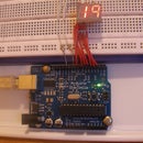
Step 7: Testing!


If everything went to plan, you should now see "Hello World" on your LCD and a counter on line 2 that increments every second.
The ShiftLCD is exactly the same as the built in LiquidCrystal library. All functions are exactly the same and everything works on the ATTiny. However, the speed that the LCD can be written at is slower. It will take about 250ms to fill an entire 2x16 LCD with characters.
However, it is pretty quick for only replacing a few digits with the setCursor function.
I hope this Instructable worked great for you.
If I made any mistakes in the pinouts, I greatly apologize and want you to tell me about the issues.
(disclaimer: I did not create the ShiftLCD library and do not have anything to do with it.)


