

Introduction: AUTOMATIC WATER TANK LEVEL INDICATOR & MOTOR CONTROL USING ULTRASONIC SENSOR


Hello every one!!!!
Nice to see you all after long back ....This is my one more creation with this we can monitor the water level of 2 numbers of water tank and control motor ...
In my home i have this problem like water tank over flows while filling up and many more water has been wasted....
To over come this problem i have created this one ...I think many of them having this problem so just try this and solve it... finally give your valuable comments and feed backs...
In this project i have used two ultrasonic sensor for two water tank and one arduino uno 3,we can switch over the sensor by changing the toggle switch.
come Let's make it.....!!!!!!
Step 1: Tools and Materials Required


- Arduino R3 - 1 no
- Water tank - 2 no's
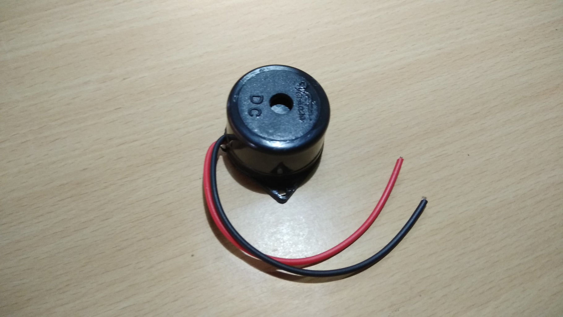
- Buzzer -1 no
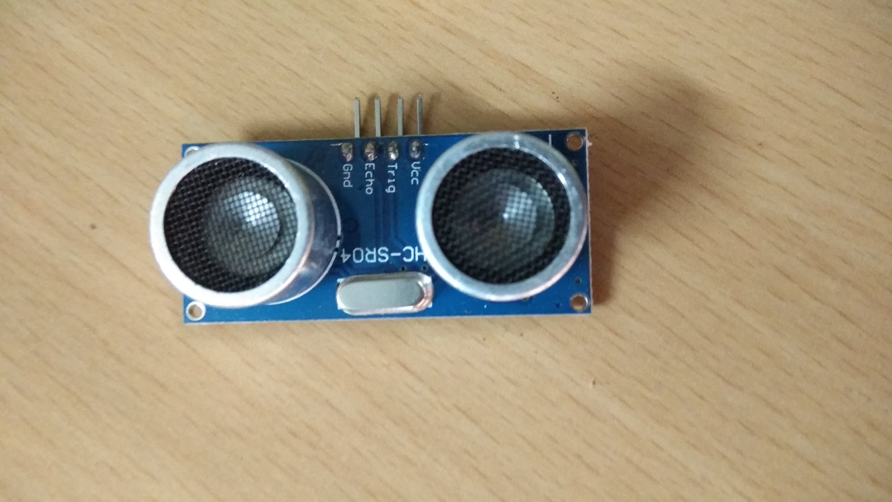
- Ultrasonic sensor - 2 no's
- 16x2 LCD display -1 no
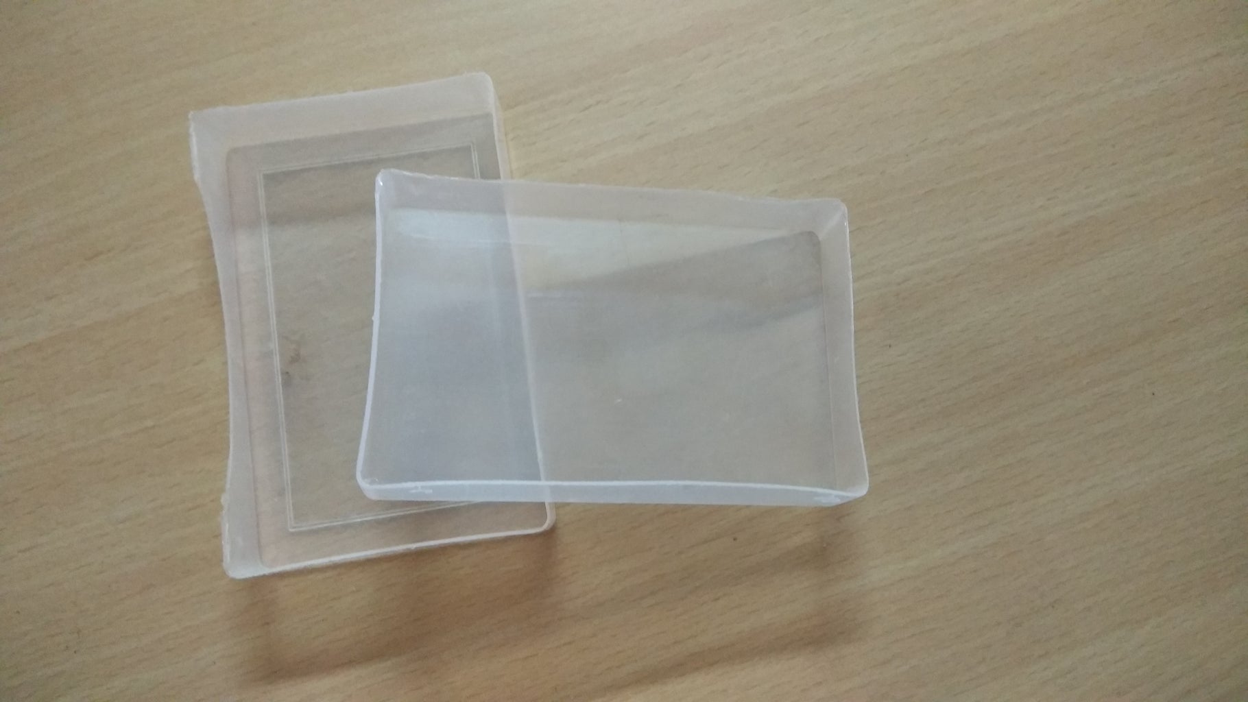
- Plastic box -2 no's
- Toggle switch -1 no
- Relay 6v/5A -1 no
- IC ULN2003 with base -1 no
- Old emergence light container -1 no
- LED's(red,yellow,green) - each 2 no's
- Ribbon wire -as required length
- 6v or 12v adapter -1 no
- General purpose PCB -as required size
- Resistor -220 ohm
- Screw -20 no's
- Plastic sheet -as required size
- Variable resistor - 10 k ohm
- Connecting wires - as required
TOOLS :
- Wire stripper - 1 no
- Wire cutter -1 no
- Soldering kit -1 no
- Hot glue gun -1 no
Step 2: CIRCUIT DIAGRAM:

In this circuit diagram i have used 3 separate toggle switch to change over between two sensors but in real single one is available and that's enough.....if you have any doubt just comment it...
Step 3: PROGRAM:
PROGRAM:
#include <LiquidCrystal.h>
#define led 13
#define led2 12
#define led3 11
#define led4 10
#define led5 9
#define led6 8
#define trigger 18
#define echo 19
#define motor 17
#define buzzer 16
LiquidCrystal lcd(2,3,4,5,6,7);
float time=0,distance=0;
int temp=0;
void setup()
{
lcd.begin(16,2);
Serial.begin (9600);
pinMode(trigger,OUTPUT);
pinMode(echo,INPUT);
pinMode(motor, OUTPUT);
pinMode(buzzer, OUTPUT);
pinMode(led, OUTPUT);
pinMode(led2, OUTPUT);
pinMode(led3, OUTPUT);
pinMode(led4, OUTPUT);
pinMode(led5, OUTPUT);
pinMode(led6, OUTPUT);
lcd.print(" Water Level ");
lcd.setCursor(0,1);
lcd.print(" b Indicator ");
delay(2000);
}
void loop()
{
lcd.clear();
digitalWrite(trigger,LOW);
delayMicroseconds(2);
digitalWrite(trigger,HIGH);
delayMicroseconds(10);
digitalWrite(trigger,LOW);
delayMicroseconds(2);
time=pulseIn(echo,HIGH);
distance=time*340/20000;
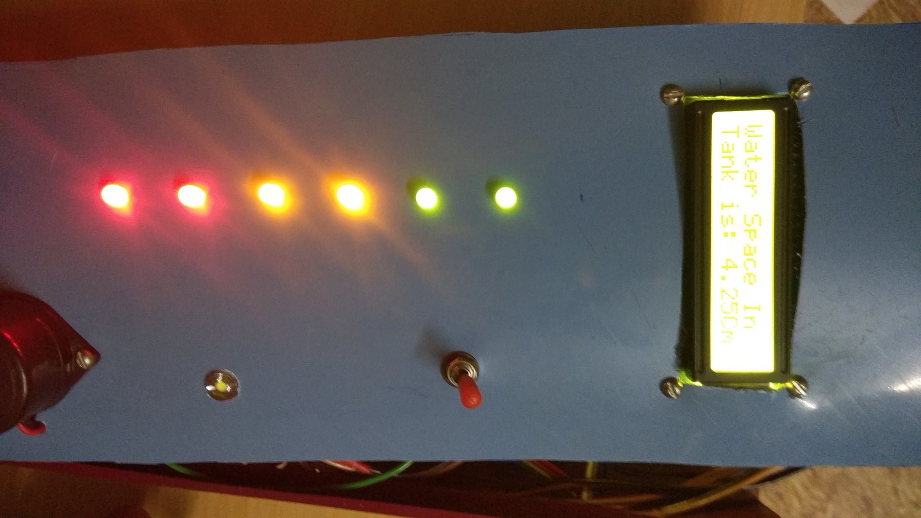
lcd.clear();
lcd.print("Water Space In ");
lcd.setCursor(0,1);
lcd.print("Tank is: ");
lcd.print(distance);
lcd.print("Cm");
delay(2000);
if (distance <= 78)
{
digitalWrite(led, HIGH);
}
else
{
digitalWrite(led,LOW);
}
if (distance < 65)
{
digitalWrite(led2, HIGH);
}
else
{
digitalWrite(led2, LOW);
}
if (distance < 52)
{
digitalWrite(led3, HIGH);
}
else
{
digitalWrite(led3, LOW);
}
if (distance < 45)
{
digitalWrite(led4, HIGH);
}
else
{
digitalWrite(led4,LOW);
}
if (distance <28)
{
digitalWrite(led5, HIGH);
}
else
{
digitalWrite(led5,LOW);
}
if (distance < 15 )
{
digitalWrite(led6, HIGH);
}
else
{
digitalWrite(led6,LOW);
}
if(distance<15 && temp==0)
{
digitalWrite(motor, LOW);
digitalWrite(buzzer, HIGH);
lcd.clear();
lcd.print("Water Tank Full ");
lcd.setCursor(0,1);
lcd.print("Motor Turned OFF");
delay(3000);
digitalWrite(buzzer, LOW);
delay(3000);
temp=1;
}
else if(distance<15 && temp==1)
{
digitalWrite(motor, LOW);
lcd.clear();
lcd.print("Water Tank Full ");
lcd.setCursor(0,1);
lcd.print("Motor Turned OFF");
delay(5000);
}
else if(distance>70)
{
digitalWrite(motor, HIGH);
lcd.clear();
lcd.print("LOW Water Level");
lcd.setCursor(0,1);
lcd.print("Motor Turned ON");
delay(5000);
temp=0;
}
}
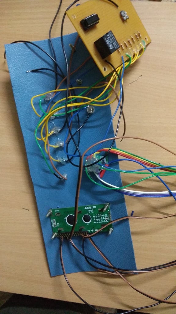
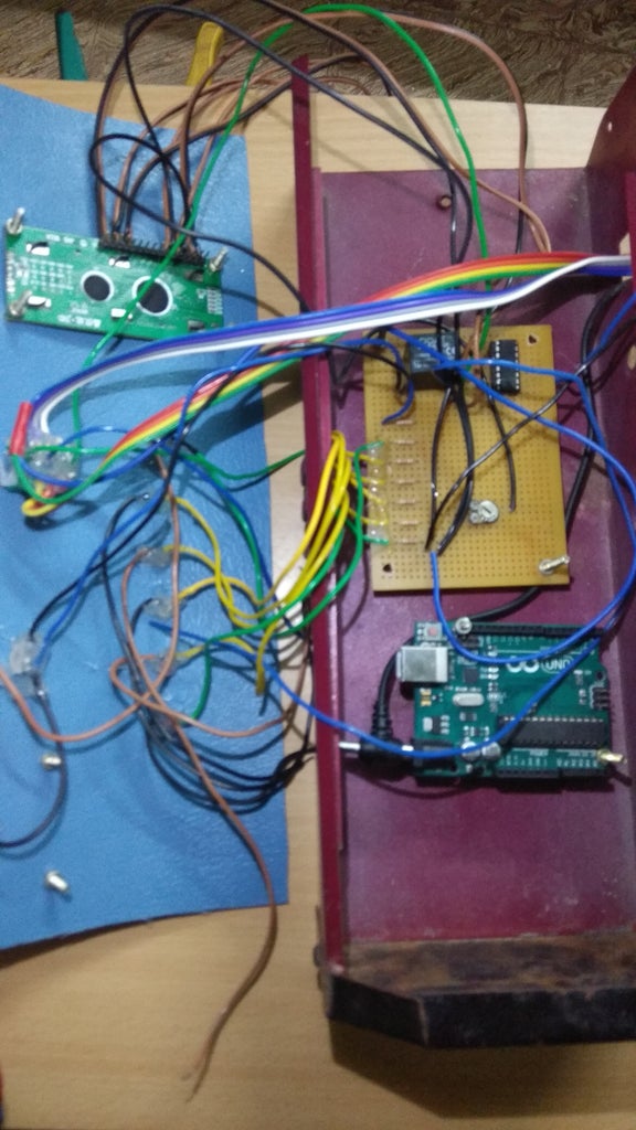
Step 4: TRIAL IT ON BREAD BOARD
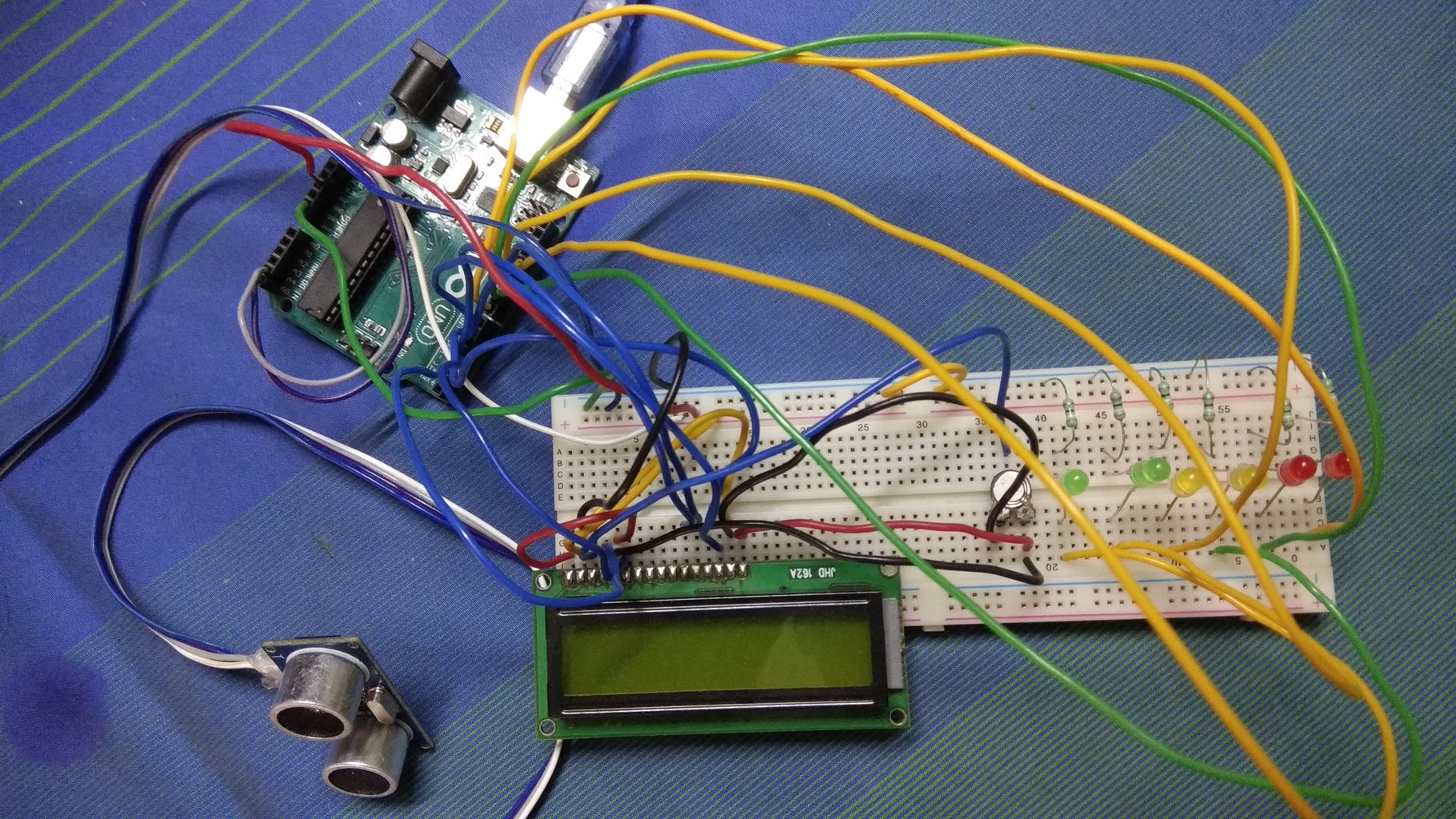
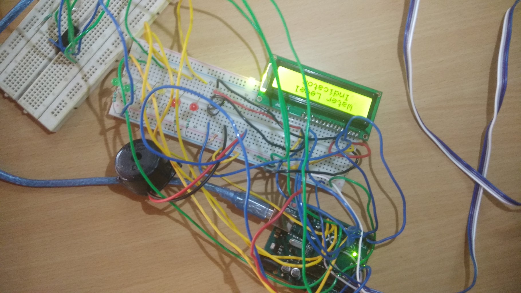
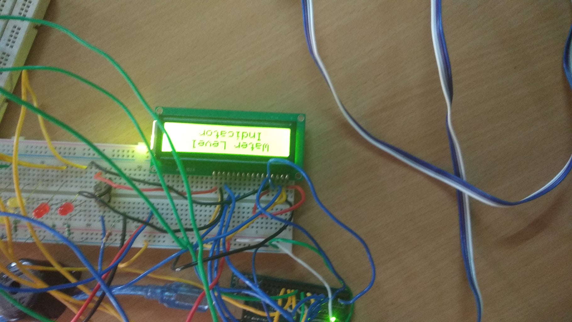
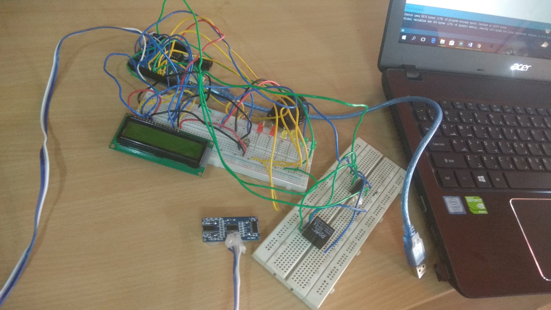


Just make the connection as per the circuit diagram and download the program to arduino board & check the output
Step 5: CUT THE PLASTIC SHEET


NOW take the plastic sheet and cut it as set in to the old emergence light box...... please refer the images attached
Step 6: MAKE a HOLE

Just place a arduino and pcb board in perfect place then mark it to fix and make holes .....
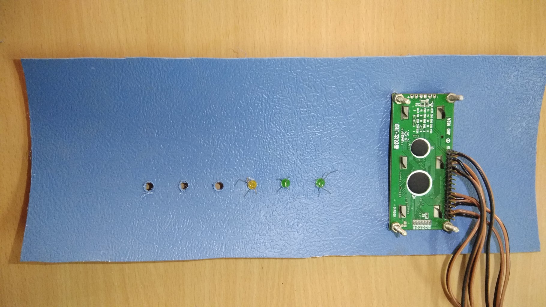
Step 7: PREPARING THE LCD DISPLAY


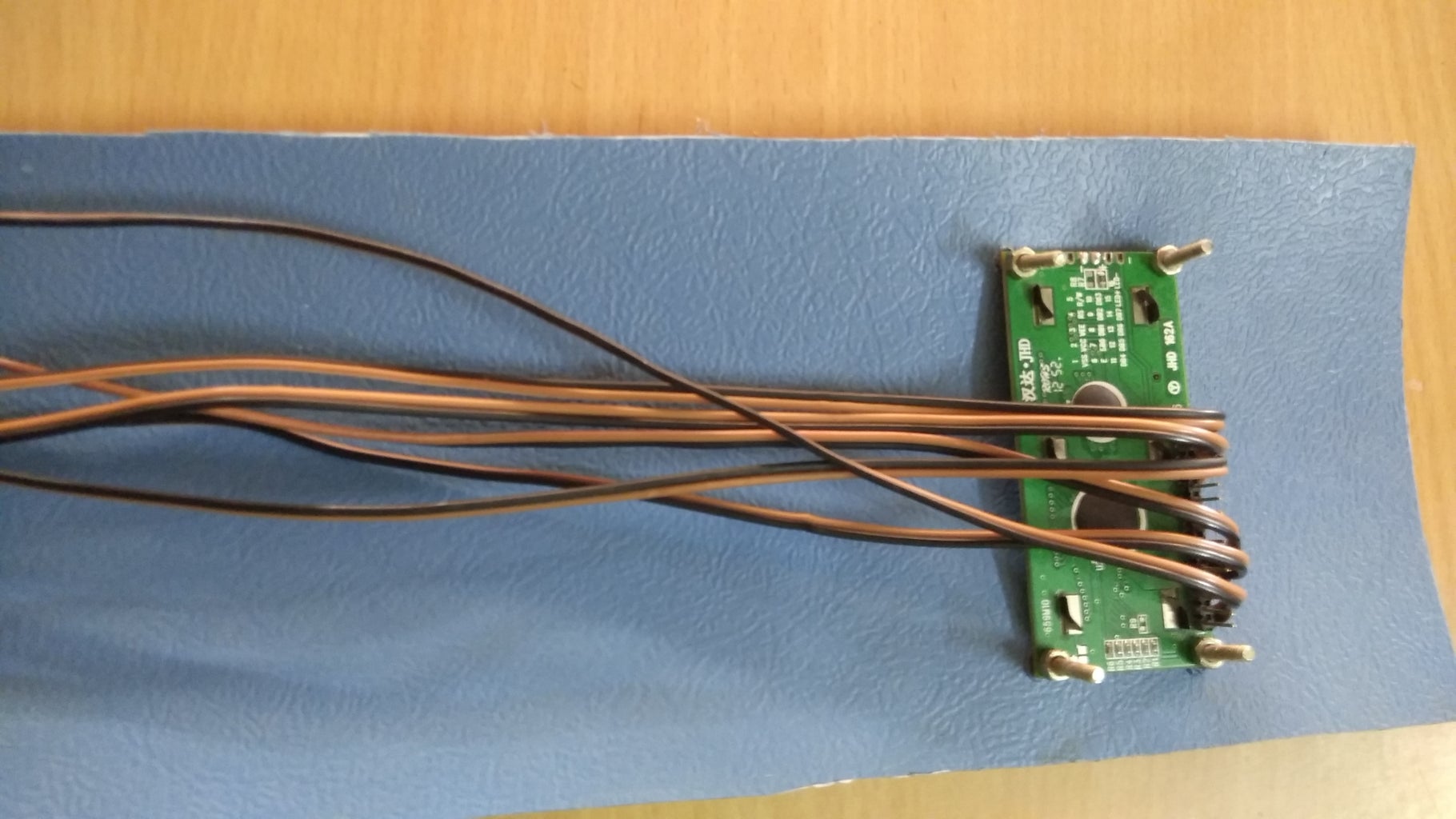

Take some wires and solder it on LCD display pins and make a hole space on plastic sheet and place it on the plastic sheet
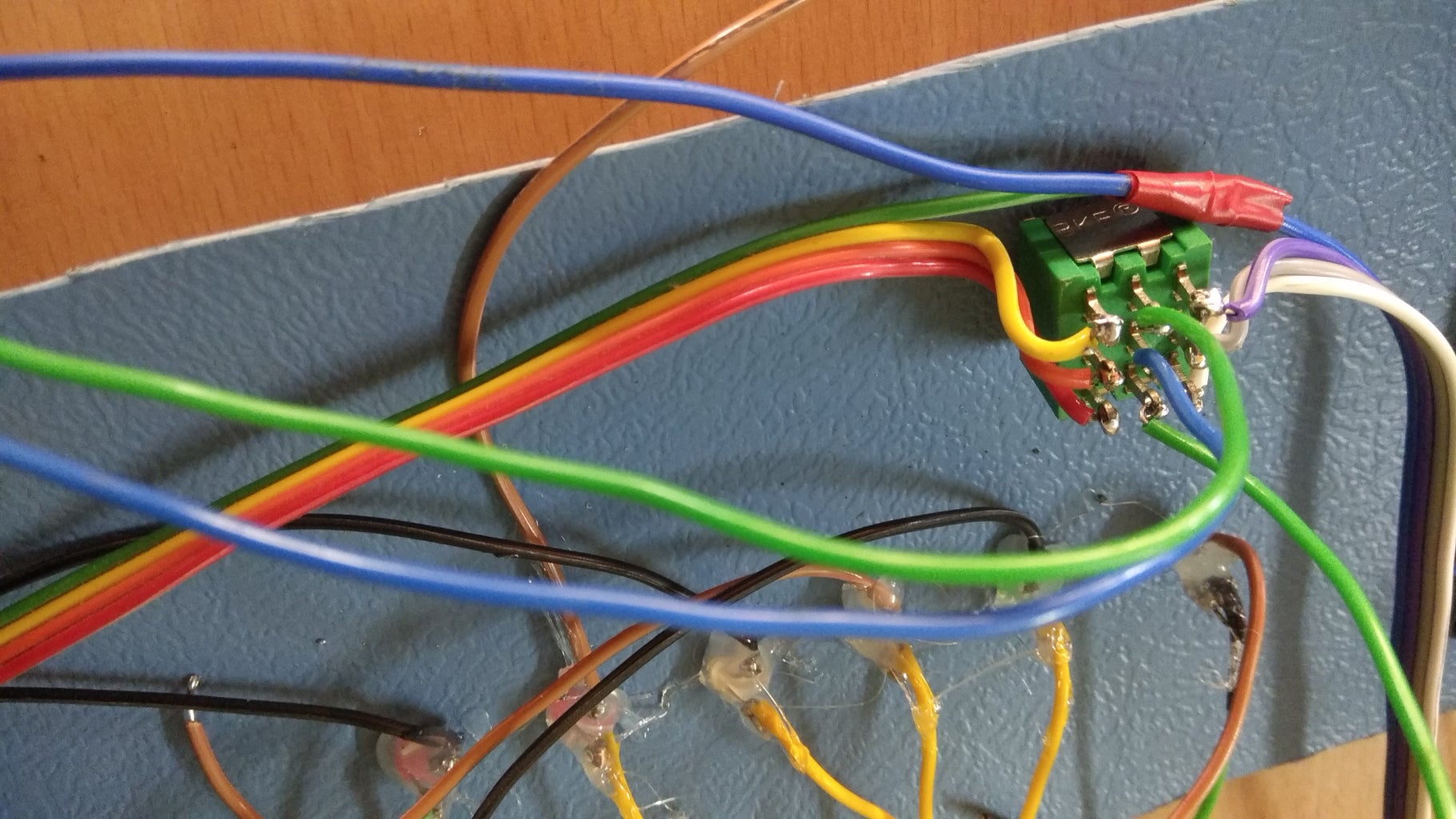
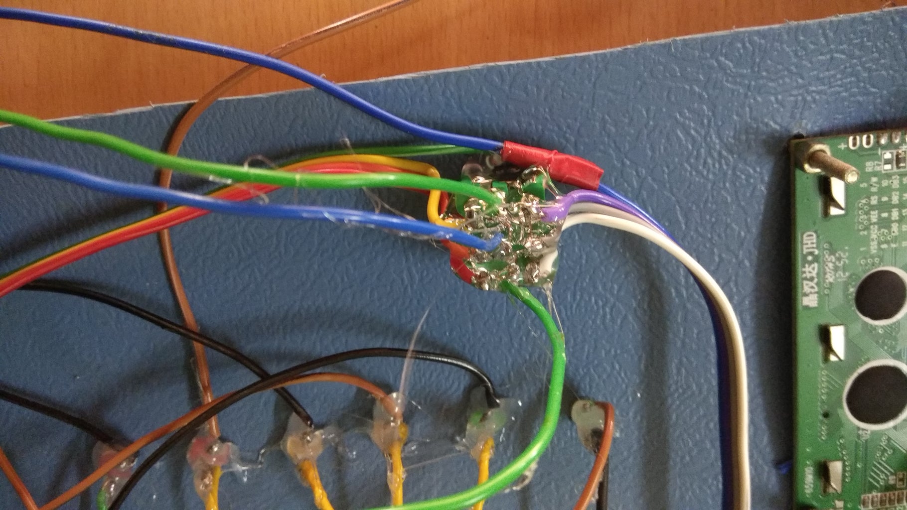
Step 8: PLACING THE COMPONENTS ON PCB


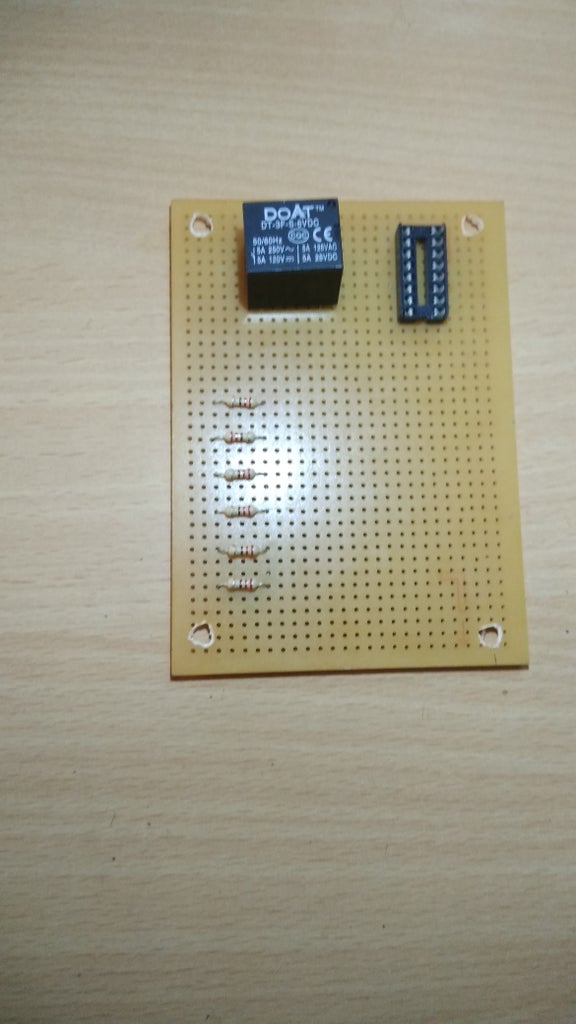

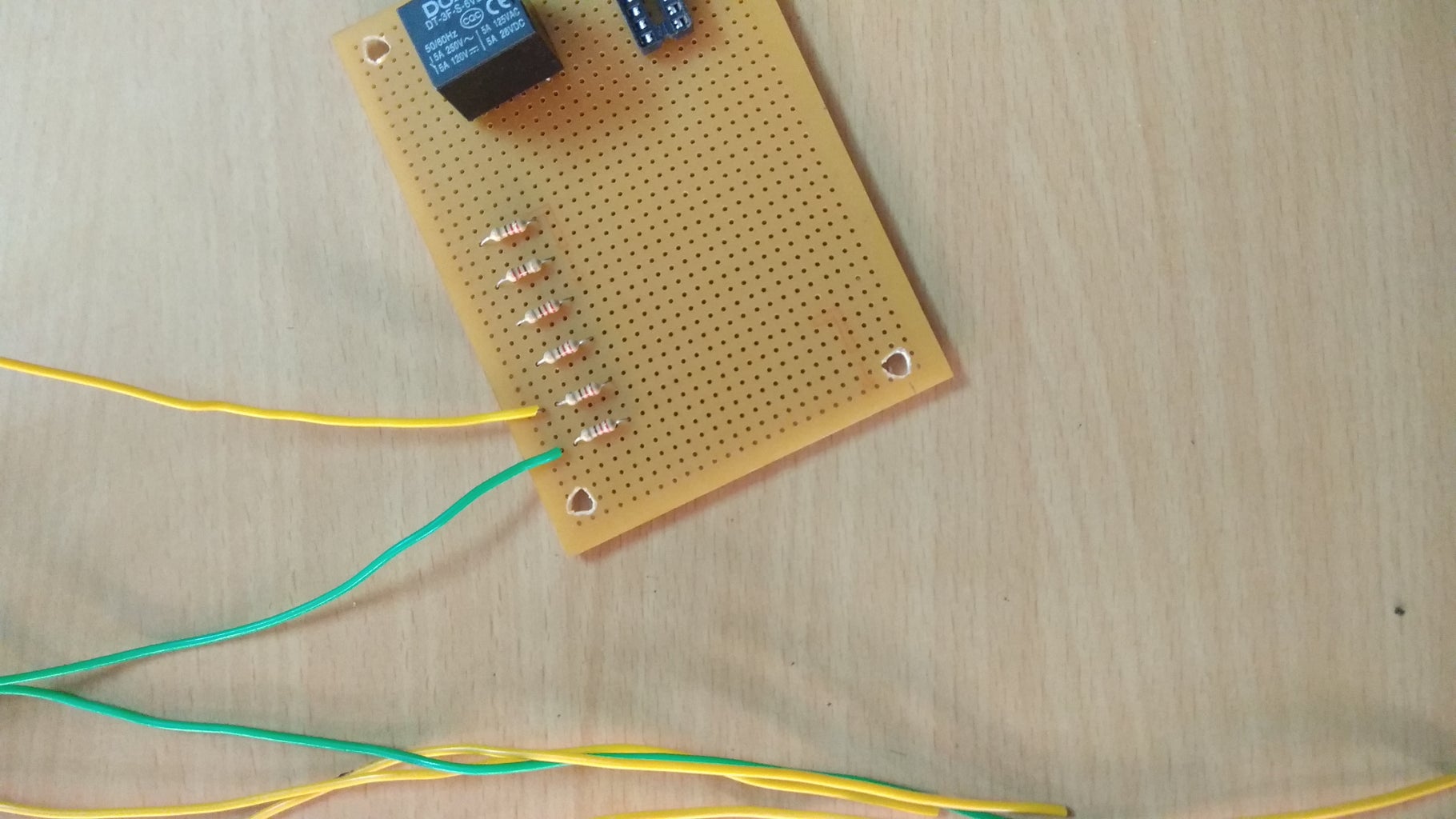
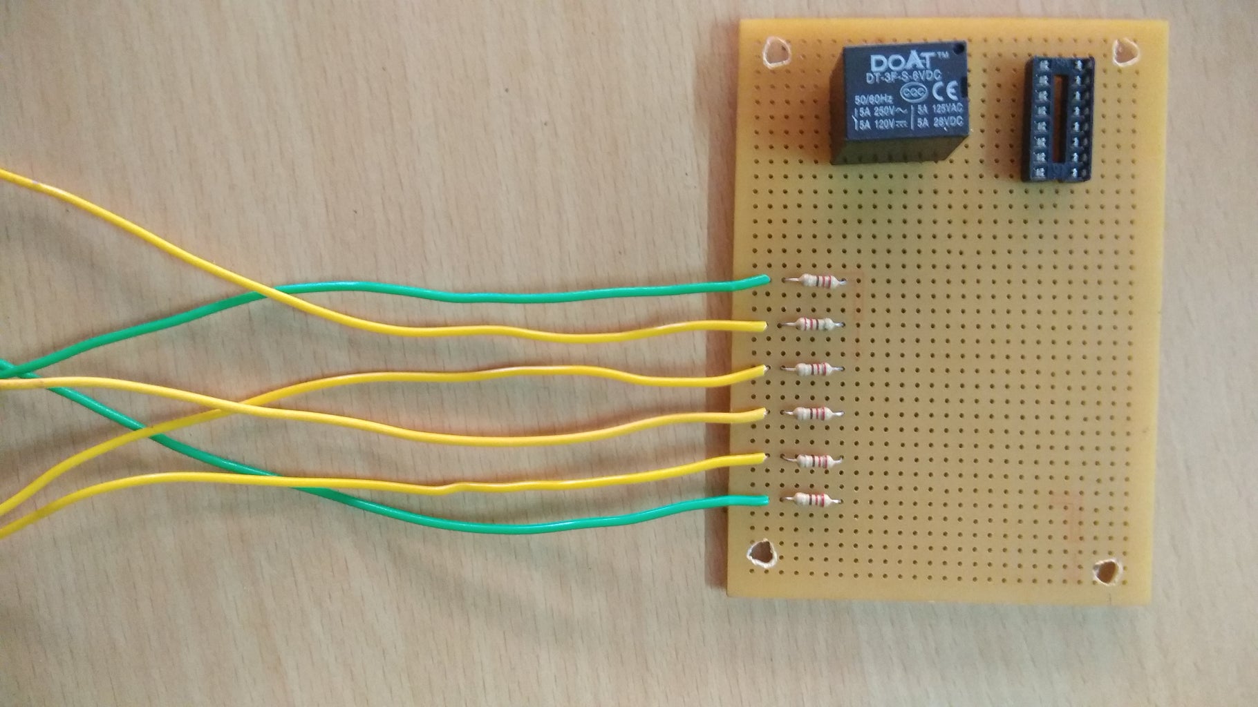


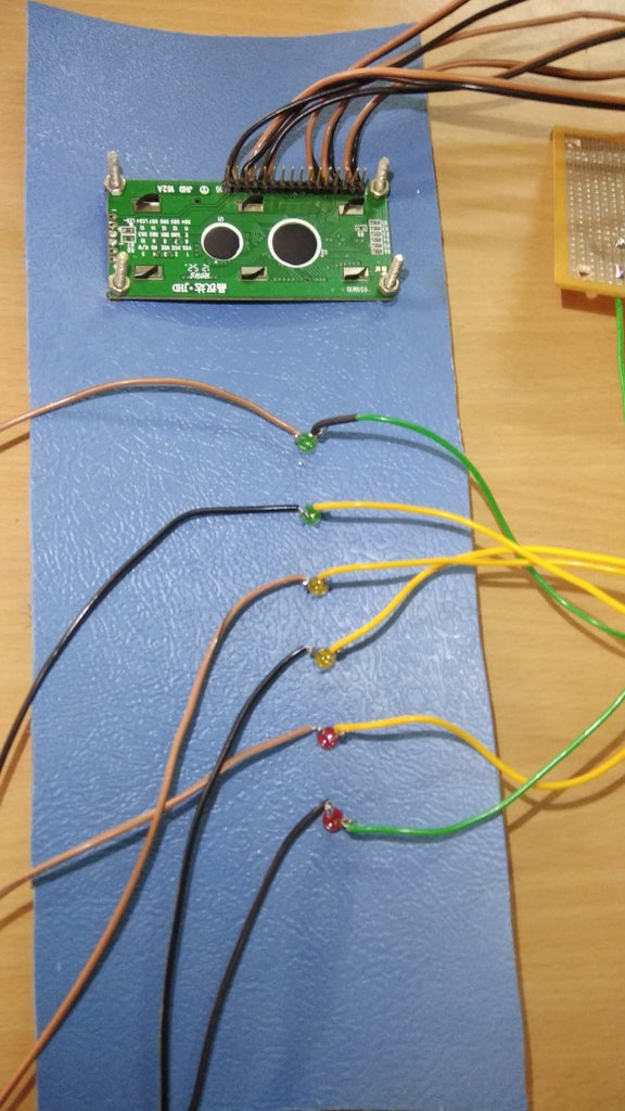
Now we are going to place the components on PCB and solder it and connect some wires to connect LED's
Step 9: FIXING AND CONNECTION OF LED'S
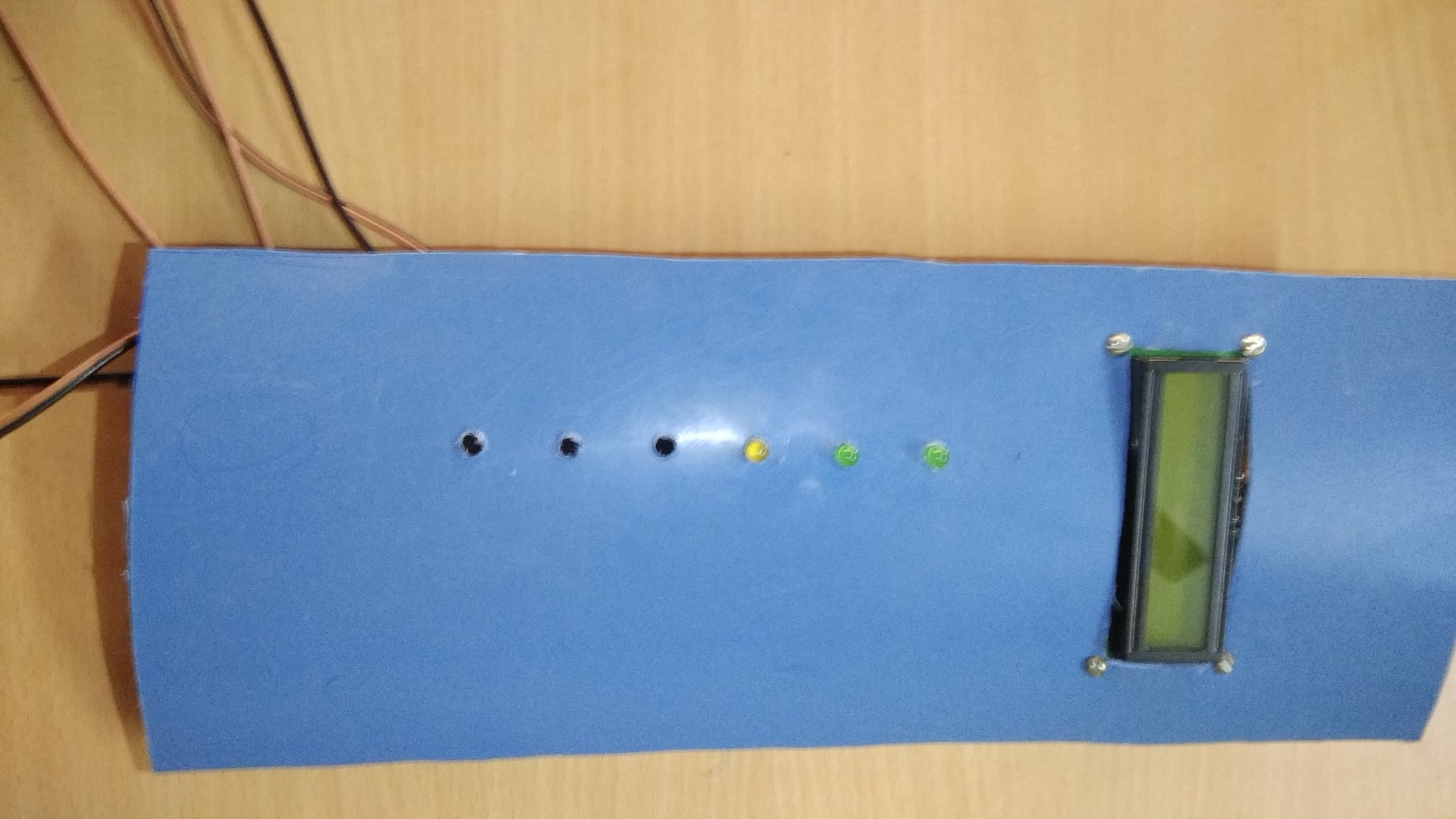


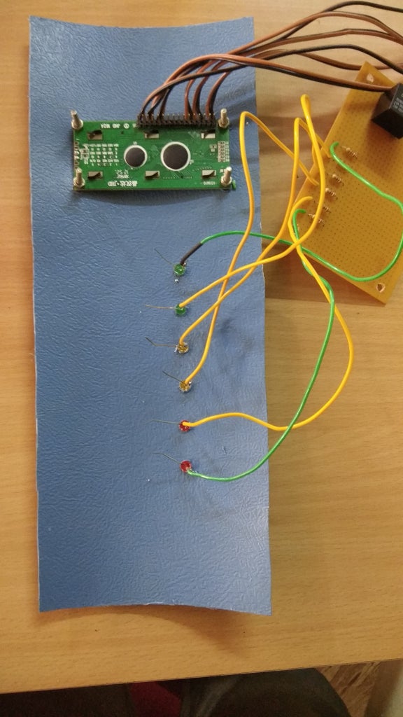
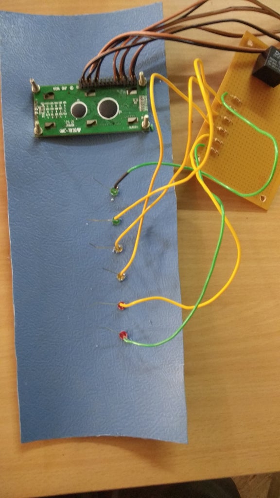

Then make make a perfect size hole to fit LED's then connect them as per the circuit diagram.
Step 10: TOGGLE SWITCH

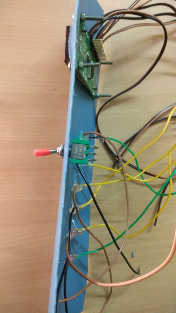


Here we are going to fix toggle switch on that plastic sheet and make connection as per the circuit diagram.
Step 11: BUZZER
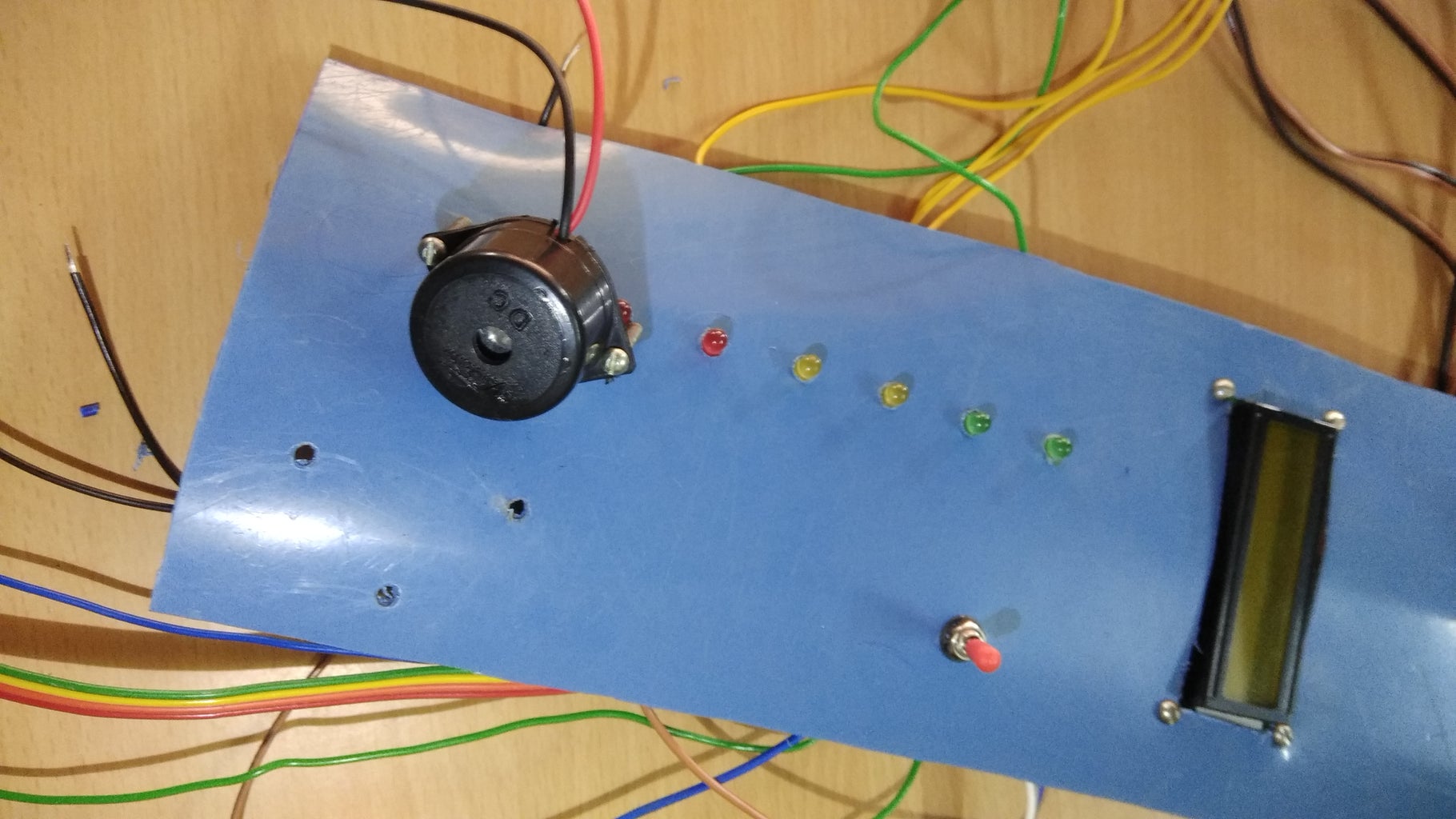
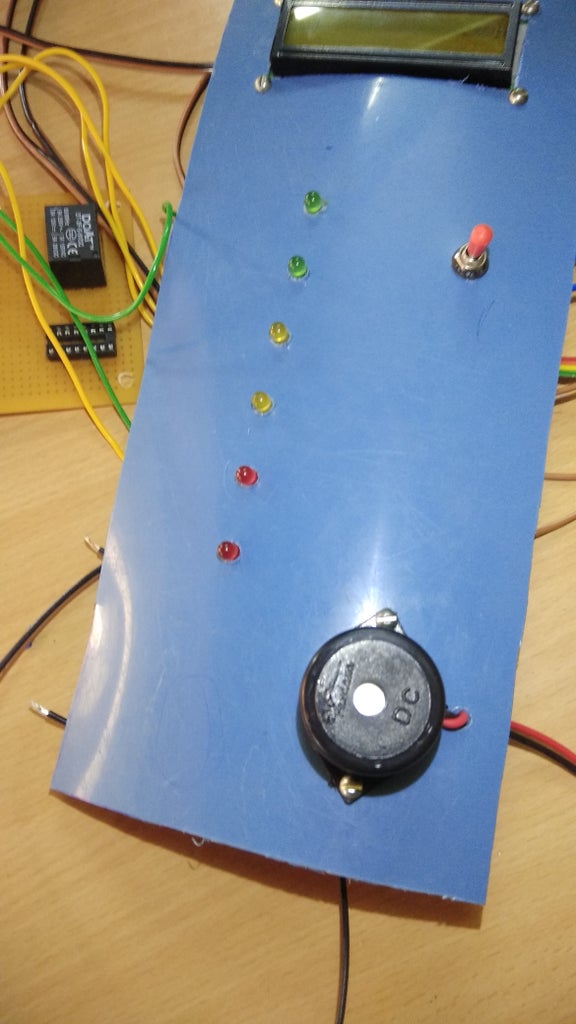
Just fix the buzzer on the sheet and make connection...
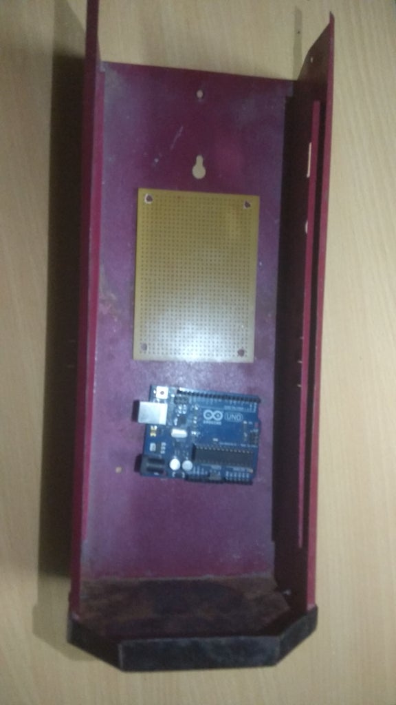
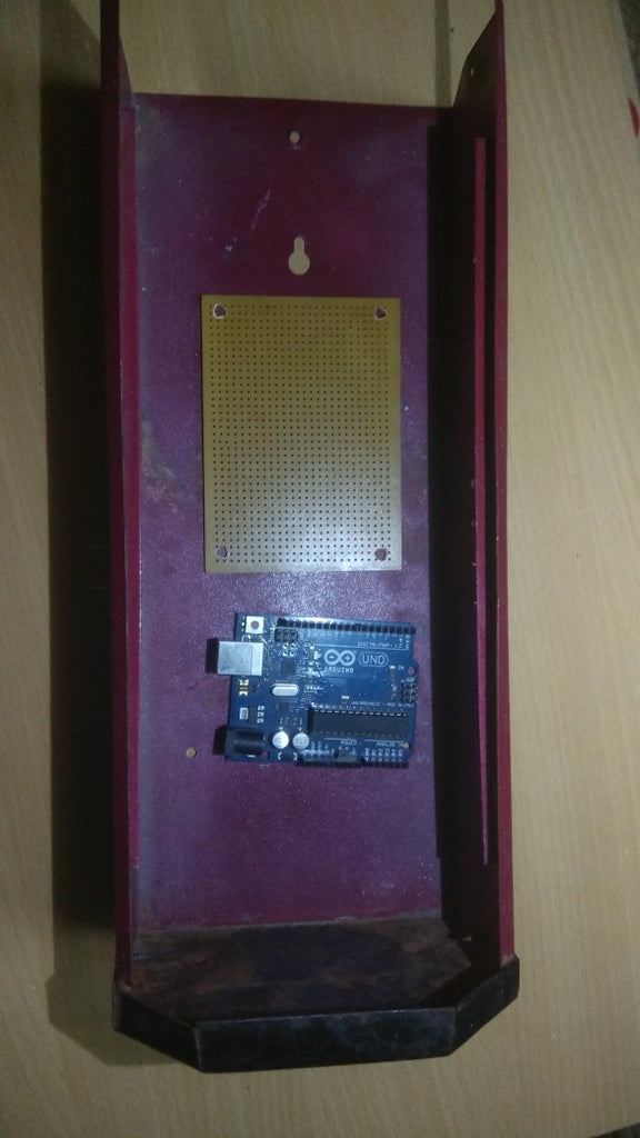
Step 12: PLACEMENT OF ARDUINO


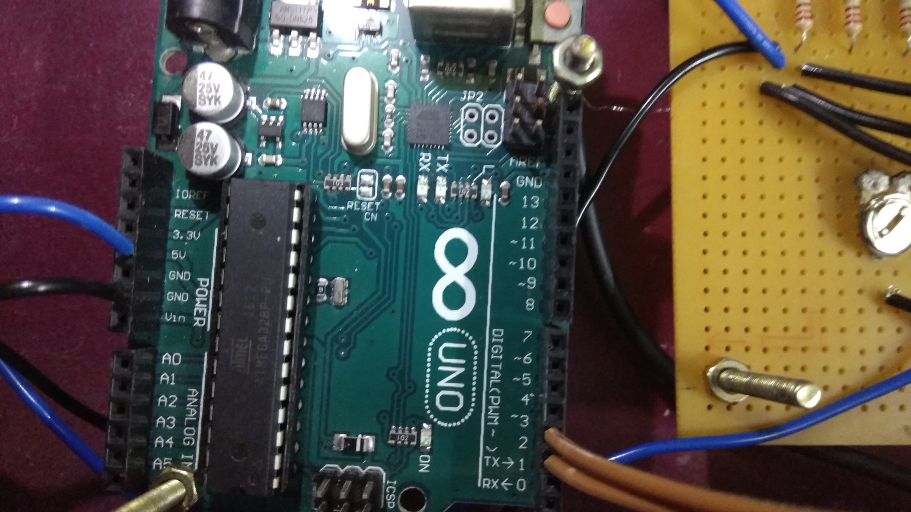
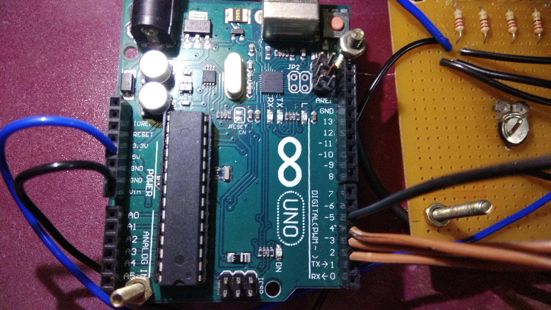
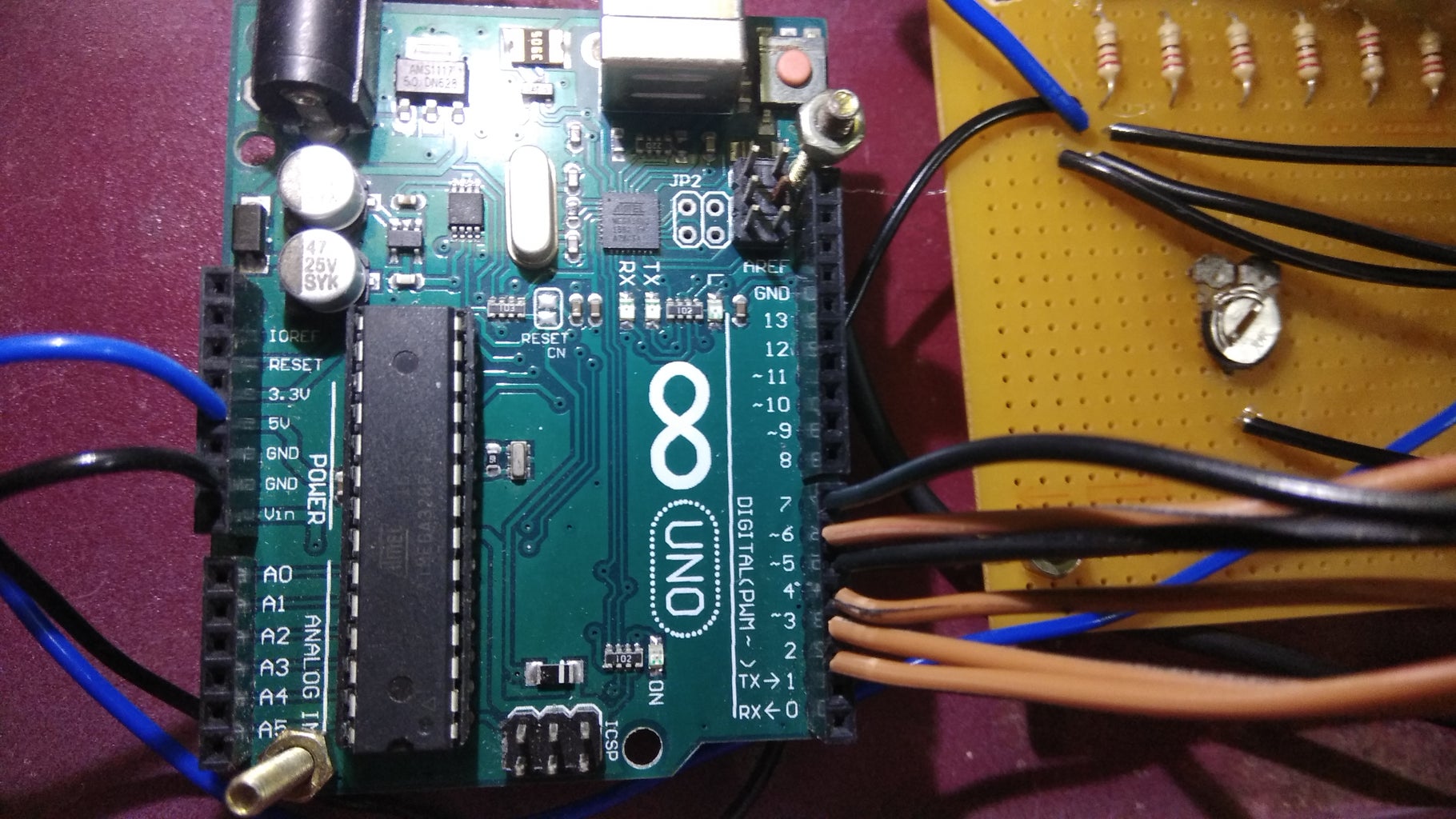

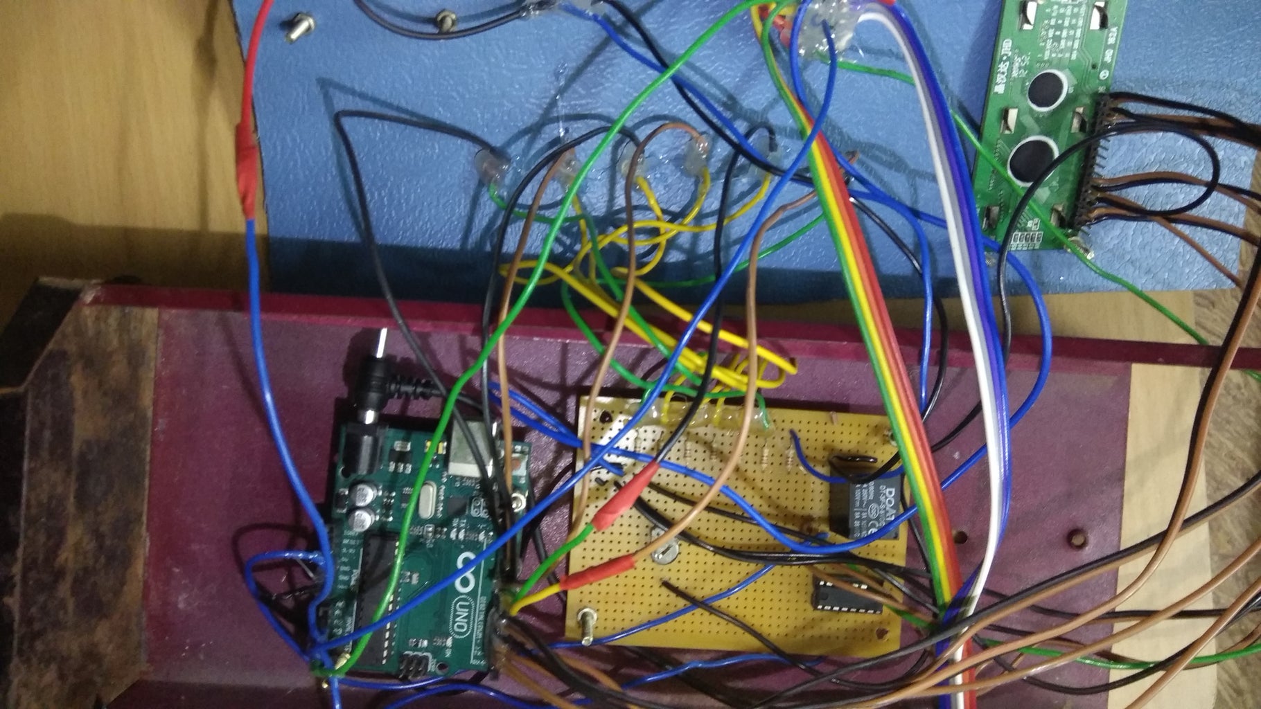

NOW place arduino and provide the connection as per the circuit diagram for more details just refer image attached
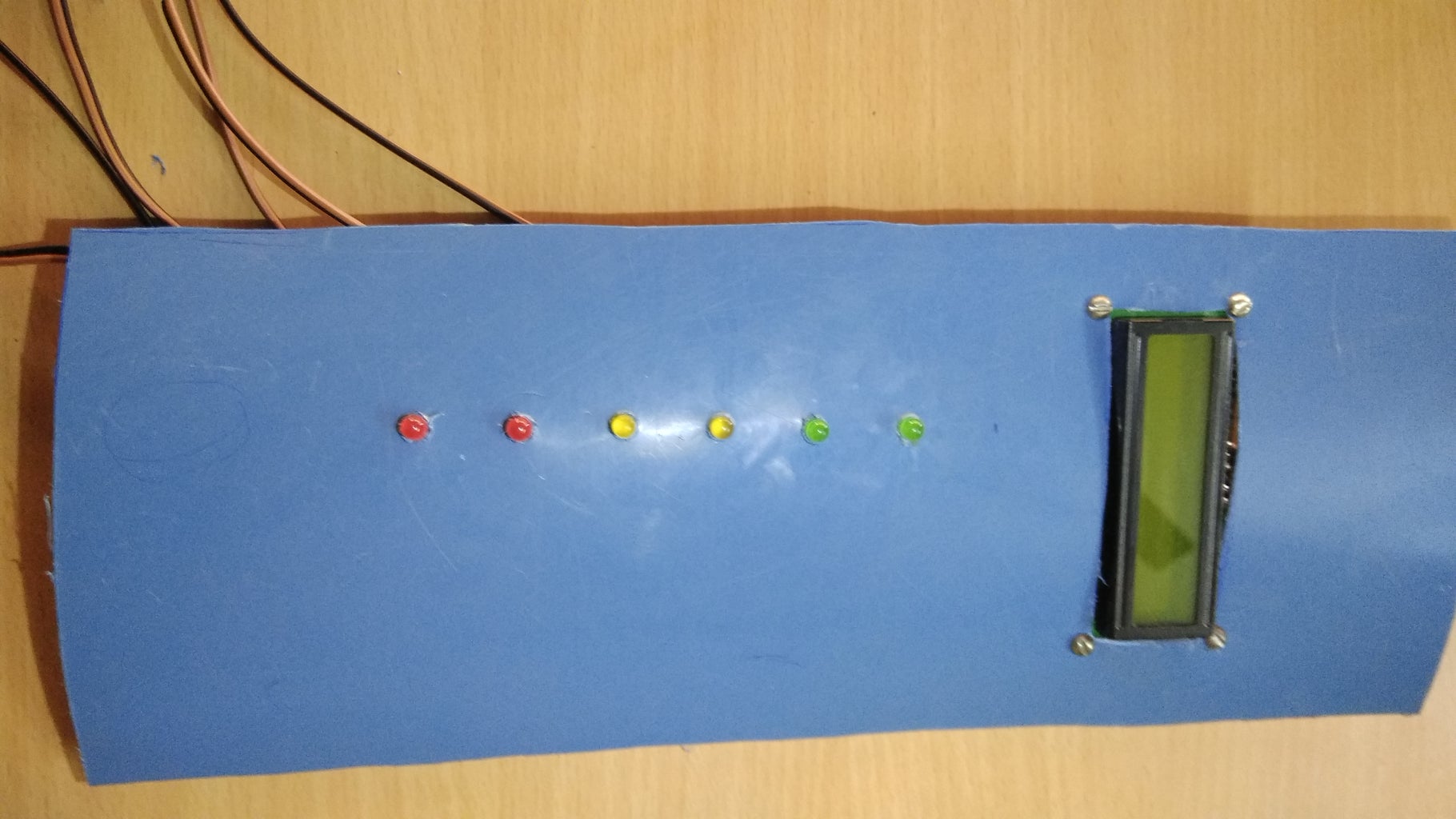
Step 13: SMALL TESTING
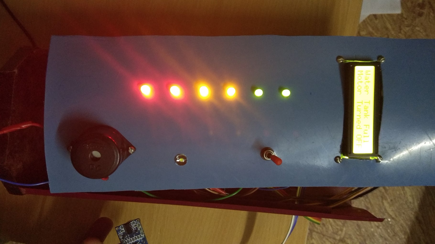
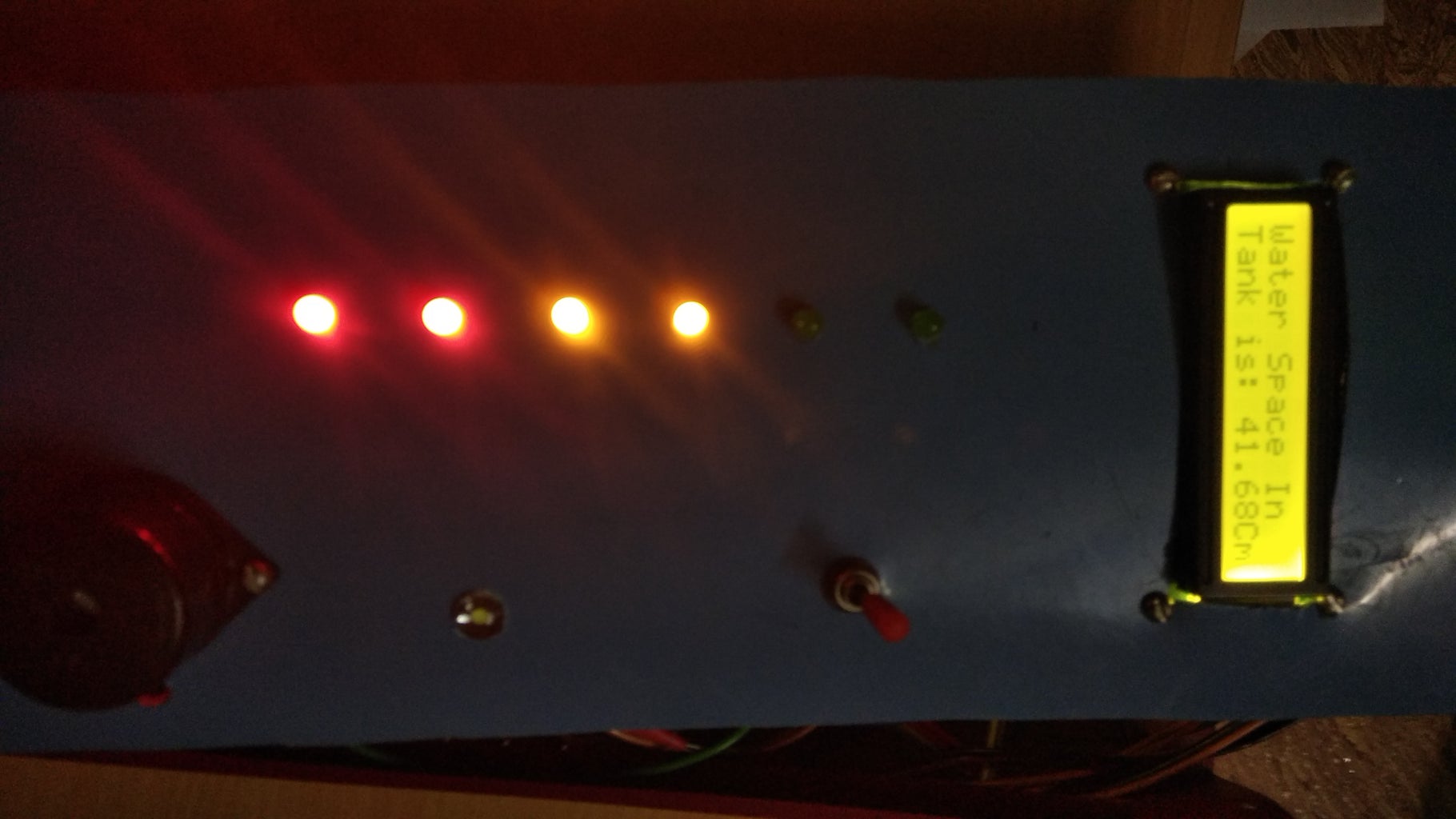


NOW power on and test the output by just lifting the ultrasonic sensor
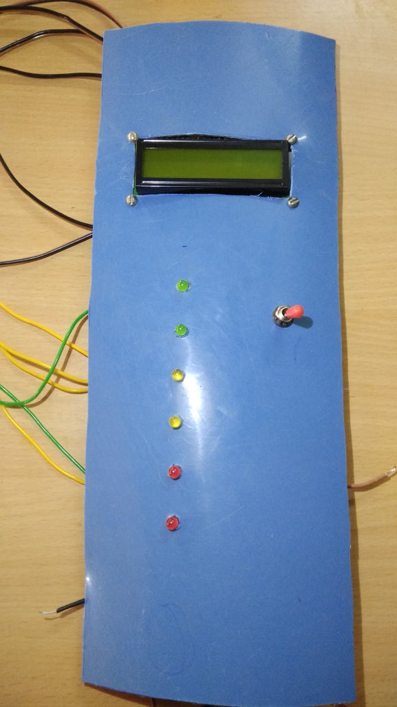
Step 14: CLOSING THE BOX


Here we are going to fix everything in to the box and closed it ....
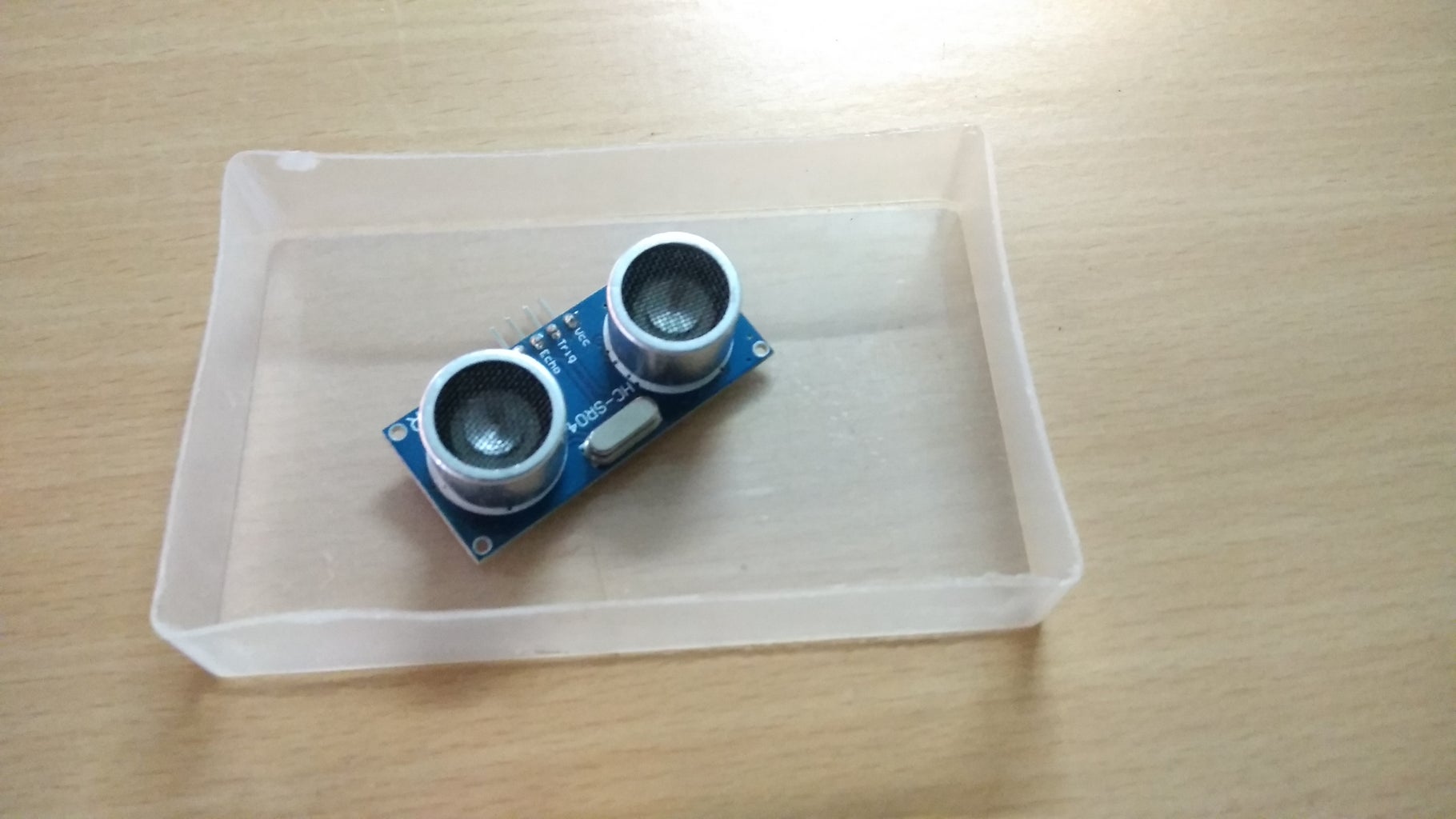
Step 15: ULTRASONIC SENOR


Then fix the sensor on the box like mentioned on image
Step 16: STICKERS


Type the letters like low,high medium,display,tank 1,tank 2, motor status, alarum in word document ..... then take printout & fix it on those place....
Step 17: PLACE SENSOR ON WATER TANK


JUST refer the image and place those sensors.
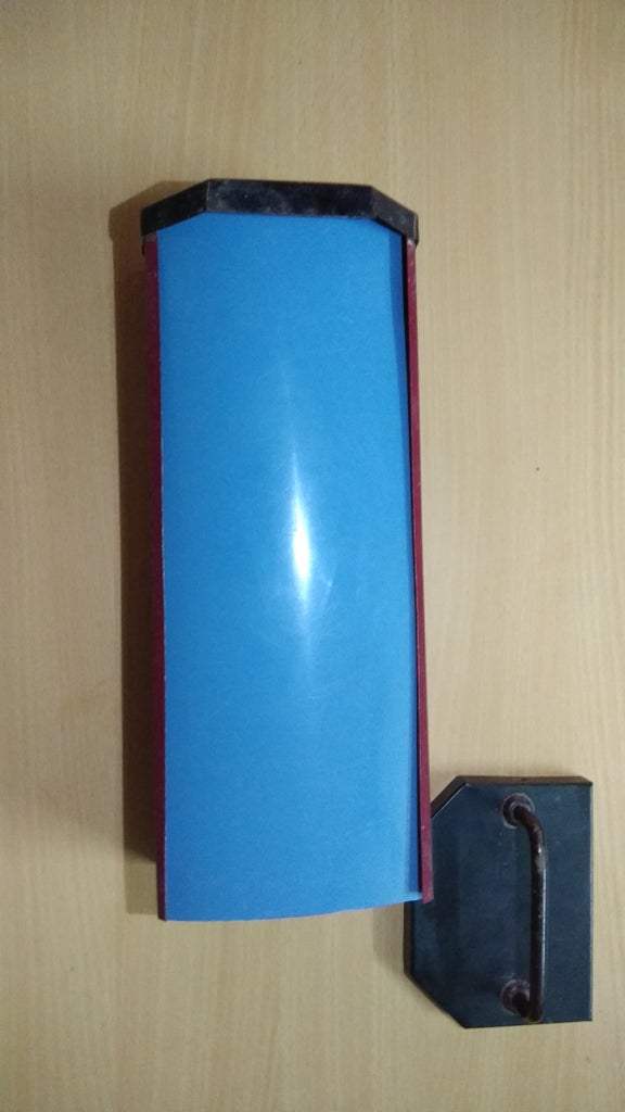
Step 18: FIX THAT BOX ON WALL


Finally fix that entire setup on the wall and switch on the circuit and watch the perfect out put
we made it !!!!!
THANK YOU .........PLEASE GIVE ME YOUR VALUABLE COMMENTS AND FEED BACKS......
YOUR'S
ANTONY XAVIER G

Participated in the
Make it Move Contest


