

Introduction: Accelerometer-logger With SD-card Memory


A logger unit for measure forces on a roller coaster and save them to a SD-card.
It's also possible to modify the software in the unit so it can measure other things if it can be connected to a i2c-bus.
Top Thrill Dragster
Step 1: Introduction
This is the fifth version of this unit (I know it's named v3, the fourth was called v3310 :) , it has also been a v0).
I have been working on this project in my spare time over two years now.
I use a LIS3LV02DQ from ST-Microelectronics to measure the forces, a uALFAT from ghielectronics.com to manage the SD-card, a HCMS2915 display and a PIC16F876 to control every thing. I also use a Canon NB-4L battery ( the same model i have in one of my cameras) to power the unit.
BOM (aka what you need) :
a PCB (a gcprevue-file to download)
a piece of Plexiglas 72.3x57x8 mm to the battery compartment
a piece of Plexiglas 3 mm thick to the front window
soldering iron with a small tip 0.4mm
some drills
some mill bits
thread cutter M3
Super glue and some regular glue stick
a X-Y table from Proxxon
a bench mounted drill
a battery (I use a CANON NB-4L).
a Microchip PICkit2 programmer.
a aluminum case 1455B802BK ELFA.se
a broken camera to get a battery connector from
and some surface and hole mounted components (BOM-file below).
Attachments

Step 2: Prepare the PCB.


The PCB is in three parts and have to be separated before they can be populated with components.
(The new PCB layout has every thing cut out if it's ordered from a board-house and just needs to be broken apart.)
Step 3: Populate the PCB.


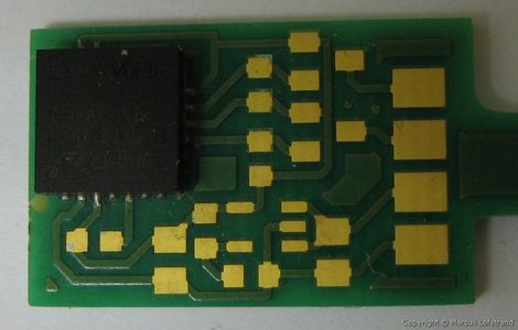
Start to populate the three PCBs. The 2 32KHz crystals has to be super glued to the PCB.
The trickiest part to solder was the sensor, that have all the connections on the bottom of the component (I borrowed the x-ray @ work to check that the soldering was perfect :) ).
Step 4: Mill Out the Plexiglas.


Start to glue a printout of the mounting drawing on to the Plexiglas using a glue stick.
Then start to measure and mill out space for the components that are to high.
Drill and cut threads in the four holes for the PCB.
Mill out the space for the battery ( you can use almost any camera battery, but it should not be bigger than 45x38x6.5mm).
Then mill out space for the battery connector ( the connector comes from a broken CANON camera :) ).
And finally mill out a canal for the sensor cable so when you pull the cable the connector don't damage.
Create a front window of 3mm thick Plexiglas.
Step 5: Final Preparations


Connect the battery and check that +3.3v_1, +3.3V_2 and +1.8V is correct.
Load the character map in to the external memory, then load a testing software to the uP to see if the unit is starting.
Prepare the sensor-board, it just need the sensor, some capacitors and a couple of wires.
Then connect the cable between the sensor and the main unit and check that the sensor is working.
The last thing to do is mount the uALFAT-chip and connect the SD-card.
Mount the PCB to Plexiglas with 4 screws.
Now you are ready to measure the forces in your car, bike and of course roller coasters. :)
Attachments
Step 6: Conclusions


So far my brother and I have measured about 200 roller coasters in Europe, Asia and USA.
The unit is versatile platform to use for logging data that is collected from sensors that is connected though a i2c-bus, the only modification to do is in the software logging-loop.
The files the unit is creating is csv-format that is simple to create graph from in ex. Excel.
The next thing to do is make a new sensor that can measure more that +/-6g in the Z-axis.
RCDB
ThemeParkReview
ThemeParkReview forum post
Ride Guide


