

Introduction: Adding an MCP23017 I/O Extender to Arduino or ESP8266


UPDATE Okt 2017: Although this works flawlessly, I would now advise against making it for the simple reason that a cheap, ready made module is available on aliexpress, the price of which rivals the price of the DIL chip alone.
I am not claiming that what I am describing here is earth shattering or trailblazing, because in fact it is very simple and no doubt has been done by many already. But sometimes what is simple for the one, is still a question mark for the other, so here is quick how to of adding 16 I/O ports to your microprocessor. This is especially handy when working with a chip like the ESP8266 that has only limited I/O. The MCP23017 is an I2C enabled 16 I/O port chip. That means that you only need 2 pins (yes with Vcc and earth it makes 4) to control the chip and the added advantage is that you can share I2C with various other devices as well.
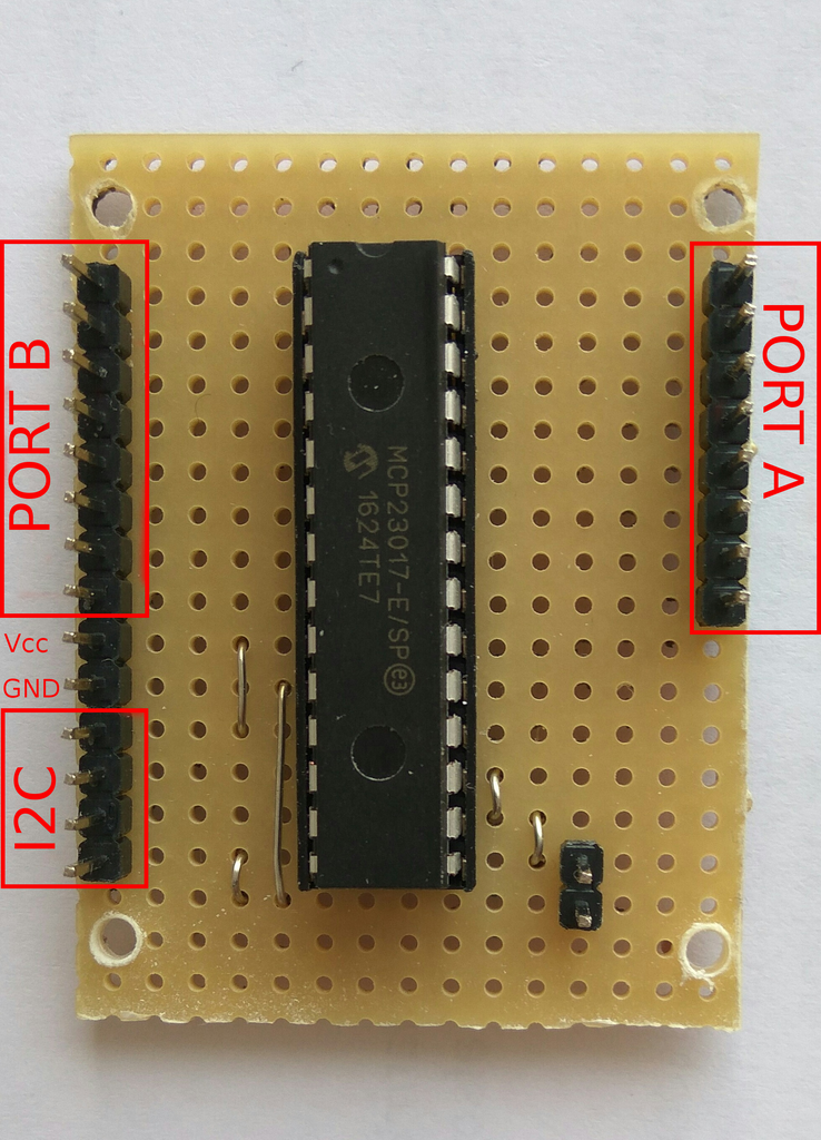
The 16 I/O lines are divided into an 8 I/O PORT A and an 8 I/O PORT B. Both can be used as input as well as output. The chip also has 2 configurable interrupts (that I will not be using). The physical layout of the chip makes it quite easy to use it on a piece of strip board.
The circuit is rather simple. At a last moment I decided to leave out the pull up resistors so it would be more flexible to use together with other I/O devices. The 3 Address pins A0-A2 determine the I2C address that ranges from 0x20 (all pins on ground) to 0x27 (all pins on Vcc). The chip can take a Vcc from 2.7V to 5V and this is perfect for 3.3 Volt devices as the modern arduino's and the ESP8266 range.
Using the chip in a program is fairly easy. There are good libraries available, but it might help if you know how to program the chip without a library. In my case I have all address lines tied to ground and therefore my I2C address is 0x20. Suppose I want to use all PORT A lines as outputs. I do that as follows:Wire.beginTransmission(0x20); Wire.write(0x00); // IODIRA register Wire.write(0x00); // set entire PORT A to output Wire.endTransmission();For PORT B that is rather similar:
Wire.beginTransmission(0x20);
Wire.write(0x01); // IODIRB register
Wire.write(0x00); // set entire PORT B to output
Wire.endTransmission();
If we then want to send a specific value 'X' to that PORT A, we do that as follows
Wire.beginTransmission(0x20);
Wire.write(0x12); // address port A
Wire.write(X);  // value to send
Wire.endTransmission();
'X' ofcourse is a byte value that determines whether we set a specific port HIGH or LOW. If for instance 'X'is '0' that means we write a LOW to all PORT A outputs. If it is 255 that means we write a HIGH to all PORT A outputs. To determine what value to send, consider the 8 I/O lines of PORT A as a byte in which the individual bits determine HIGH or LOW. So if we only want to make PORTA.0 HIGH and the rest LOW, we write a binary value of 0b00000001 =1 to the A register. If we want to make PORTA.0 and PORTA.2 HIGH and the rest LOW we write a binary value of 0b00000101 = 5. For PORT B it is similar:
Wire.beginTransmission(0x20);
Wire.write(0x13); // address PORT B
Wire.write(X);  // value to send
Wire.endTransmission();
If we want to use PORT B (or PORT A for that matter) as input, we do that as follows:
Wire.beginTransmission(0x20);
Wire.write(0x13); // address PORT B
Wire.endTransmission();
Wire.requestFrom(0x20, 1); // request one byte of data
byte input=Wire.read(); // store incoming byte into "input"
The byte "input" will vary between 0 and 255, in which the individual bits determine the input on the corresponding IO line. So if 'input' reads '3' which in binary is 0b00000011, that means that both IO line 0 and 1 were HIGH and the rest LOW
#include <Wire.h> // Wire.h
byte input=0;
void setup()
{
  Serial.begin(9600);
  Wire.begin(); // wake up I2C bus
  Wire.beginTransmission(0x20);
  Wire.write(0x00); // IODIRA register
  Wire.write(0x00); // set entire PORT A as output
  Wire.endTransmission();
}

void loop()
{
  // read the inputs of PORT B
  Wire.beginTransmission(0x20);
  Wire.write(0x13);
  Wire.endTransmission();
  Wire.requestFrom(0x20, 1);
  input=Wire.read();

  // write that input to PORT A
  Wire.beginTransmission(0x20);
  Wire.write(0x12); // address PORT A
  Wire.write(input);    // PORT A
  Wire.endTransmission();
  delay(100); // for debounce
}
That's basically it if you want to do the adressing yourself. Using a library, such as the one from Adafruit, makes it much easier though as it has commands to write and read from individual IO lines. One of the example programs to read a single button, looks for instance like this: #include <Wire.h> // Wire.h
#include "Adafruit_MCP23017.h"
// Basic pin reading and pullup test for the MCP23017 I/O expander
// public domain!
// Connect pin #12 of the expander to Analog 5 (i2c clock)
// Connect pin #13 of the expander to Analog 4 (i2c data)
// Connect pins #15, 16 and 17 of the expander to ground (address selection)
// Connect pin #9 of the expander to 5V (power)
// Connect pin #10 of the expander to ground (common ground)
// Connect pin #18 through a ~10kohm resistor to 5V (reset pin, active low)
// Input #0 is on pin 21 so connect a button or switch from there to ground
Adafruit_MCP23017 mcp;
void setup()
{
mcp.begin(); // use default address 0
mcp.pinMode(0, INPUT);
mcp.pullUp(0, HIGH); // turn on a 100K pullup internally
pinMode(13, OUTPUT); // use the p13 LED as debugging
}
void loop() {
// The LED will 'echo' the button
digitalWrite(13, mcp.digitalRead(0));
}


