

Introduction: Android & Arduino Controlled Projector Screen


Why (Problem)
I love watching sports, my family loves watching sports, and we all love cheering on our local college team (Go Dawgs). This leads to lots of watch parties on game day. Since there are usually upwards of 15 people we use a projector so everyone has a good view. The downside is the screen. In the past this was just a white sheet tacked to the wall. This was decent but left a lot to be desired.
What (Solution)
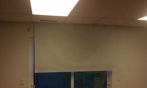
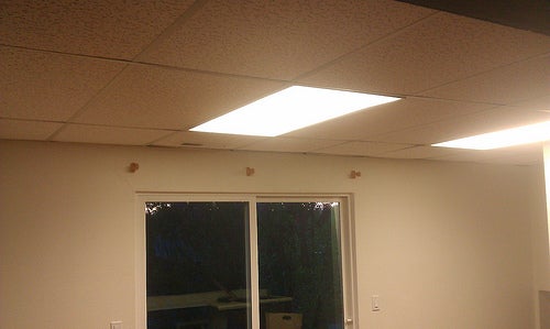
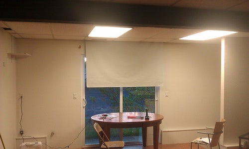
A motorized, Android and Arduino controlled, Bluetooth enabled, screen. The screen itself is made of white blackout material, giving a smooth bright projection surface. The whole unit is stored above a drop ceiling which the screen is deployed through, into the room (if you don't have a drop ceiling where you use your projector don't worry, you can just mount to the ceiling or wall).
New Screen Pros
- Storage - With a push of a phone button the screen is stored out of sight, in the ceiling.
- Setup - With a push of a different button the screen is deployed and ready for use. No more thumbtack holes in the wall or ironing a sheet that was folded up and creased.
- Picture Quality - The blackout material screen does not allow projected images to show through to the back or let ambient light from behind seep through. Also no more having to iron your sheet/screen before use or waves and wrinkles in the screen.
- Wow Factor - Because it's awesome, enough said.
- Cost - A similarly sized, motorized screen will run you $300, or up to $1500 for a in-ceiling model!
- Cost - A white sheet from Wal-Mart is probably a few bucks, where as an Arduino UNO alone is close to $30.
Step 1: Materials and Tools


- Arduino UNO- $27, Amazon - I used an UNO because this is my first Arduino project and figured it would be best to start with the base model. You probably can use other microcontrollers, feel free to use your favorite.
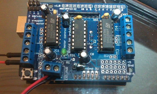
- Arduino Motor Control Shield - $10, eBay - I went for simplicity over cost and just bought a pre-built, albeit off-brand, motor controller. Mine is based around the L293D chip.
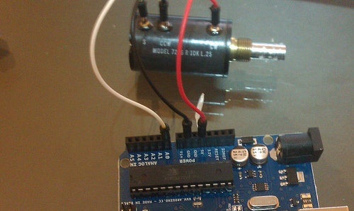
- High Torque Gearbox DC Motor - $10, eBay - You can calculate an approximate torque requirement, formulas and calculation walkthroughs on the next page. Make sure voltage and current requirements don't exceed what your motor controller can provide.
- 10kOhm, 10 Turn Potentiometer - $10, eBay - Used as a limiting sensor. The pot needs to have more turns than it takes to wrap the screen around the rod. If you are going with a huge screen, or a long drop, you can use a gearbox to reduce the turns on the pot.
- Bluetooth Serial Adapter - $9, eBay - You can use a Sparkfun BlueSMiRF which is easier to use but much more expensive. The off brand ones are also very small which is great for space requirements but can be harder to solder depending on which unit you get. If you can find one with pins and a cable I would recommend it.
- 10 kOhm Resistor - Not needed if you use a BlueSMiRF or other 5 V Bluetooth module.
- 20 kOhm Resistor - Not needed if you use a BlueSMiRF or other 5 V Bluetooth module.
- 2x 9 V Battery - Powers the Arduino and motor. You may need more or less voltage for you motor, scale appropriately or use AC adapters if you have a socket available.
- 2x 9 V Battery Clip/Holder - See above.
- 53" x 2 Yards White Blackout Material - $7/yrd, Jo-AnnFabric - This is enough canvas to make an 80" screen (70" x 40", 16:9) with room for the drop down out of the ceiling. If you want a different size screen check out this site.
- 1-3/8" DIA x 6' Closet Rod - $10, Lowes - Adjust the length of this piece based on the screen size, width specifically, you select. If you have a different size screen, calculations for determining minimum diameter are on the next page.
- Flange Nut/Panel Nut - Match the the threads to those on your pot. This nut should have ridges in the face to keep it from backing off when tightened (Flange nut only, add a star washer with panel nut.)
- Motor Mount Screws - My motor had two threaded holes in it's face for mounting. Yours may have more or less and are probably a different size.
- Rubber Grommet - The inner diameter matches, or is slightly smaller than, the diameter of the potentiometer's shaft.
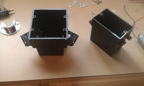
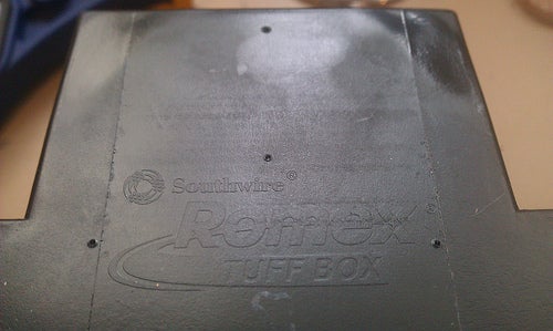
- 2x Wall Box - One houses the potentiometer, the other holds the motor and Arduino. You are looking for boxes with a flat surface big enough that the rod won't hit anything with enough space inside for the components.
- Set Screw -Diameter: Should be as large as possible while still fully engaging the motor's shaft, mine was #10. Length: Longer is better but it must be longer than half the difference between the O.D. of the motor grommet and the motor output shaft O.D.
- Hanger Tape - $2.50, Lowe's -Used to reinforce my drop ceiling since some of the structure had to be cut.
- Glue/Epoxy/Bonding Agent - Must be able to work on multiple materials.
- Jumper Wires - I got a bunch of Arduino specific jumper wires off of eBay. They are nice because you get the easy soldering and header compatibility of a solid core wire with the flexibility of a multi-strand.
- Scrap Wood - Used to build a structure for holding the whole unit above my drop ceiling.
- Wood Screws, Washers, Misc Hardware
- Arduino Paraphernalia - USB cord, Arduino software
- Android Development Paraphernalia - USB cord for your phone, Android Development Software (for if you know Java), or the MIT/Google App Inventor (What I used, is powerful enough for our use).
- Soldering Equipment - Iron, solder, de-soldering wick/bulb, helping hand.
- Drill & Drill Bits
- Compass
- Center Punch
- Level
- Tape Measure
- Hacksaw
- Other Basic Tools
Step 2: Calculations


Use the THIS great website to decide on a screen size. Here are some things to consider when picking a screen size.
- Room size - Check out the viewing distance calculator on the page above.
- Available material size
- Projector abilities
Motor & Rod Calculations
Once you've decided on a overall size based on room size, available space, optimal viewing distances, etc. you should run some quick calculations to determine how much minimum torque you will probably need from your motor. The numbers in these calculations are examples, you will need to input your own values.
Find
- Minimum torque required to lift the screen from fully down. Variable = Tm
- Maximum rod diameter. This controls the number of times the screen will warp around the rod. Variable = d
- Material weight. Usually in oz/yrd2 . Variable = w, for this example w=10oz/yrd2
- Gravity, 9.81 m/s2. Variable = g.
- Screen size. Variables = height = H, width = W. For this example H = 53 in, W = 84 in.
- Maximum turns. variable = t. For this example t = 9, which leaves 1/2 turn of the pot on the top and bottom (5% of the total turns top and bottom).
- Find the area, A, of the screen in square yards.
- Find the mass, m, of the material in kg.
- Find the force, Fg, due to gravity and mass, of the screen in newtons.
- Find the diameter, d, necessary for the rod, in cm. C = circumference.
- Find the minimum torque, Tm, required to be provided by the motor, in N*cm, assuming the motor acts on the very center of the rod, the weight of the rod has a minimal moment of inertia and mass, and that the screen is hanging from the "9 o'clock", 90º, position.
Now you know exactly what you need in a motor and rod. When trying to find a motor for the most part lower RPMs means higher torque. I found a few motors that were rated 12V, 60 RPM that had a stated torque of 30 N*cm as a point of reference.
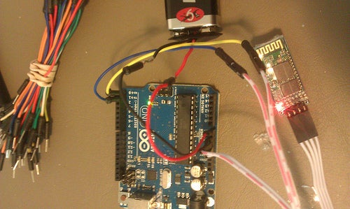
Step 3: Circuitry Introduction

Since the circuits, besides maybe the software, take the most time due to testing and troubleshooting we'll begin there. There are three separate circuits interfacing with the Arduino: the motor and it's controller, the Bluetooth module and it's Android interface, and the potentiometer. Each page describes how to setup the relevant circuit and provides a test program, in both code and plain text so you can review the code without the Arduino software installed, that tries to mimic how the circuit will be used in the final product. The circuits can be assembled and tested in any order.
Step 4: Motor Circuit


Getting the motor running is pretty simple because of the motor control shield. Its just a matter of getting wires plugged in the right places.
Circuit
Start by attaching leads to your motor if this hasn't been done already. These don't need to be really long, a few inches, but it is easier to cut them shorter than longer later, so err on the side of caution. With the motor shield attached to your Arduino, place one of the motor leads into the MA1 slot and the other into the MA2 slot on the motor shield. Grab one of your 9V (or otherwise if needed) battery clips and place the black, ground, wire in the GRD slot on the shield and the red, positive, wire into the Vcc slot, again on the board. That's it, quick and painless, or so it seems so don't celebrate until you've ran the test program below or developed your own.
Testing
Attached is an Arduino program to test the functionality of your motor. The program simply runs the motor in one direction for 5 seconds, waits for 3 seconds, reverses the motor for 5 seconds, and waits 3 more seconds and repeats this ad nauseum. If your motor control shield is different you probably will have to rewrite the motor controls in all the sketches. My shield came with a library, I don't know if this library is universal or if it is specific to the L239D chipset. Also attached is the necessary library if you want to give it a try (It's the zip file).

Step 5: Potentiometer Circuit


The pot is used to tell the Arduino what position the screen is in.
Circuit
Your pot should have three posts, make sure there is a lead wire attached to each one. These wires will probably need to be fairly long, as they will eventually reach from one end of the screen to the other where the Arduino is located. For now just attach jumpers to the pot and plug them straight into the Arduino. The three posts on the pot should be arranged with two on the outside and one between them. Connect the V+ pin to the 5V Arduino pin and the V-, or GND, post to the Arduino's ground pin. The third, or sweep, pin is attached to an analog pin, I used A0. The motor shield I bought covers all of the header pins on the Arduino but breaks them out on the board. This is fine, it just means I had to solder the pot to the motor shield for the final build. For testing the pot I just attached the pot straight to the Arduino's headers.
Testing
The attached test program uses the pot to control the built in pin 13 LED on the Arduino in a similar fashion to how it will control the motor in the final program. The program sets the top and bottom 5% of the analog input as thresholds, then as you sweep the pot the LED is on between the thresholds but turns off when you get close to the limits of the pot.
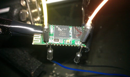
Step 6: Bluetooth Circuit

The Bluetooth module is the bridge between the Android app and the Arduino.
Circuit
Before you start you need to check the voltage requirement for your module. Many of these modules require 3.3V which the Arduino can provide without problem but the digital Tx output pin on the Arduino is 5v so you will have to build a simple level shifting voltage divider. Before you build the shifter solder leads onto the Bluetooth module. You need a lead on the Rx, Tx, 3.3V, and GND pins. Now for the level shifter grab the 10 and 20 kOhm resistors. Attach one leg of the 20 kOhm resistor (or 2x 10kOhm resistors in series) to ground, and the other to one leg of the 10 kOhm resistor. Add the end of the Bluetooth modules Rx pin to the connection between the two resistors. Finally connect the the other leg of the 10kOhm resistor to the Arduino's Tx pin. The last three connections from the Bluetooth module are simply GND to Arduino GND, 3.3V to Arduino 3.3V, and Tx to Arduino Rx. Once again the Arduino's headers are covered by the motor controller on the final build. Thanks to a1r, without whose Instructable I would have probably cooked my first Bluetooth board.
In the end I got a different Bluetooth module off of ebay that had the Vcc, GND, Tx, and Rx lines boken out to header pins and included a header cable. This unit was also 5v meaning the level shifter was not necessary. If you have a 5v module simply connect Vcc to the Arduino 5v pin, GND to Arduino GND, Tx to Arduino Rx, and Rx to Arduino Tx.
Test
This test program for the Bluetooth also doubles as the test program for the Android app. A simple test you can run before getting into the Android stuff is to simply check if your phone can pair and connect to the Bluetooth module. The actual test code below blinks the led slow for 10 seconds when up is pressed in the app, and blinks the led fast when down is pressed in the app. It also cancels the led if either button is long clicked. Remember that the Bluetooth needs to be unplugged from the Arduino while you upload the sketch.
Step 7: Assemble the Final Circuit


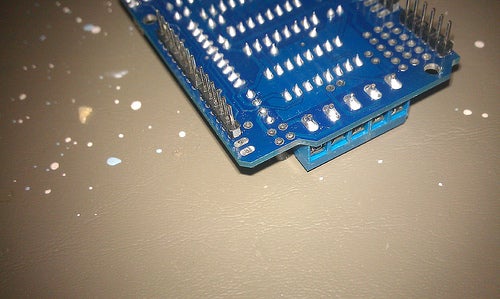


Because I bought a much cheaper motor control shield the unused pins did not have headers but, for the most part, they were broken out into through hole pads on the shield. This was the case for the 5 volt pin, GND pins, and analog pins, meaning I simply had to solder the leads into the proper holes, but not the digital pins 0 and 1 for the Bluetooth. To get access to the digital pins I de-soldered and pulled out the pins and then broke off the short plastic headers. This left just enough room to put a jumper wire bent 90º in the Arduino's headers. For the Arduino power and the Bluetooth module I soldered and attached the leads directly between the components and the shield. For the potentiometer, which will be on the opposite end of the rod, I attached short jumpers to both the pot and the shield which will be connected with long wires later. This approach allows me to easily change the distance between the Arduino and the pot meaning I can upgrade to a larger screen easily in the future without messing with the Arduino.
Step 8: Arduino Software

With the Arduino side hardware fully assembled, it's time to load the final program to your Arduino. If you don't care how the program works just download the sketch below and load it to your Arduino, if you do care keep reading. There is a .txt version of the code attached as well so you can view it without the Arduino software.
Once the program starts and everything is initialized in the setup the Arduino begins waiting for serial input to become available. When a command, a single byte, is sent from the app the Arduino saves the command, either a '1', '2', or '3', and then decides whether to put the screen down, up, or cancel current movement. This decision is based on two things, First, if the command was a 1, 2, or 3. Second, what position the screen is already in, based on the potentiometer's reading. If the screen is up and a down command is received the Arduino turns the motor on in the down direction and begins monitoring the pot's output. When the pot's value hits the lower threshold the motor is stopped and we loop back to the beginning, waiting for another command. If the screen is down and the command received was up then the processes is the same for down except the motor is halted when the pot reaches the upper threshold. If a '3' is received while the motor is running it halts the motion and the program begins again from the beginning. Any other time a '3' is received it is ignored. All other serial commands or combinations, screen up with up command or screen down with down command, are ignored and the Arduino keeps checking the serial port for commands.
As with the motor test program, if your motor control shield uses a different library you will have to correct all the motor calls in the program. (The motor shield's library is attached to Step 4.)
Warning: If you use a screen with a different height you MUST calibrate the thresholds in the program to prevent overshooting the up and down positions!
Attachments
Step 9: Android App


In simple terms the app first connects to the specific Bluetooth module attached to the Arduino with a press of the Bluetooth symbol button in the app (The module must first be paired. This is a one time operation done outside the app). Once a connection is made you can either select a button to bring the screen up or one to put the screen down. When the down button is picked a single byte, '1', is sent over the Bluetooth connection to the Arduino which then does it's thing. For up the byte '2' is sent. The long click action for both up and down sends the byte '3'. Long clicking the Bluetooth button disconnects the module.
Attached is the Android source code (zip file) so you can view it, mod it, and deploy it with your computer, via USB. The .apk for unmodified installing is attached as well. Currently the app may have to personalized for your Bluetooth module. So far I haven't had any luck getting the app to pick the module itself so I put the address of my BT module in directly. I'm not a BT expert so I don't know if the address is unique to each module or if two of the same modules will have the same address. You can find your modules address in your Bluetooth settings or with any number of free apps. If I ever get this worked out I will upload the app to the app store.
LINK to the full size image of the code blocks. Sorry there are no pictures of the actual app, you have to have a rooted device to take screenshots.
Attachments
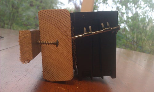
Step 10: Prepare the Rod


There are several methods you can use for finding the center of the dowel. I tried using calipers set to the radius, using a square to find diametrical lines, and finally settled on using a compass. If you have a better or different method please post it for others to see.
- Cut a small disk off the end of the rod. The raw end of my rod was not very smooth which made marking hard.
- Find the radius of the rod. Don't go off of what the lumber yard said, it most likely is not that size. My rod had slight bulges at two points so I tried to pick a decent average radius.
- Set your compass to the radius and make sure it is tight enough it won't slip.
- Place the point of the compass as close to the edge of the rod as possible and then sweep a mark across the area the center should be. Avoid placing the point on any irregularities or bulges.
- Repeat Step 4 at a point that will create a near perpendicular mark with the first. If you want more confirmation you have found the center, repeat again from a third position.
- You can check how close your center is by placing the point of the compass on the center mark and sweeping a full circle. Don't worry about minor variations, the grommet will absorb those.
With one side done move to the other repeating the steps above. The two exceptions are: cut the rod to length first ( the width of the screen plus leave an inch or two on each side, maybe more in case of mistakes), and drill the hole to the exact size of the motor shaft.
Finally to make sure the motors rotation is transferred to the rod it is secured with a set screw. Drill a hole, just smaller than the thread size of the screw, on a center line through to the axial hole you have already drilled. This position of the hole is a little tricky, to close to the edge and the threads will split the wood. To far away from the edge and the screw won't seat completely on the shaft. With a clearance hole drilled, use the set screw to cut threads, or if you have a tap use that of course. When cutting the threads, run the screw backwards and forwards as you go, don't just run it all the way down. You will get much nicer threads if you do this.
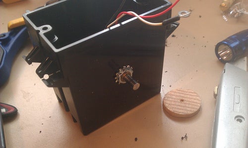
Step 11: Build the Housings


The potentiometer is mounted in one of the wall boxes, probably the smaller of the two.
Start by finding a flat spot on one of the sides of the box and marking the spot you want the pot's shaft to stick out with your center punch. Now drill a clearance hole at the mark just big enough for the threads and any bosses on the pot to pass through. Place the pot in the box and put the shaft and threads through the hole, orienting the wires so they come out the top of the box. Fix the pot in place with the flange nut, or panel nut and star washer.
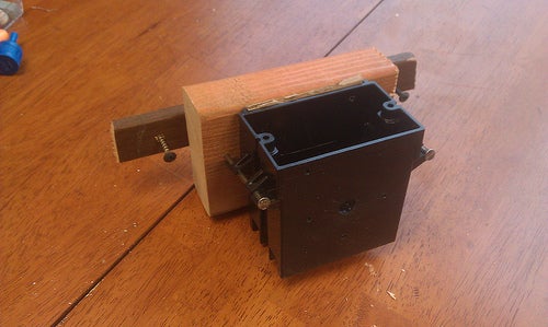
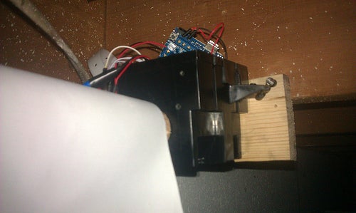
Motor and Arduino Housing
Similar to the housing for the pot but larger so it can hold the motor and the electronics.
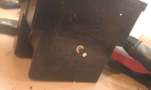
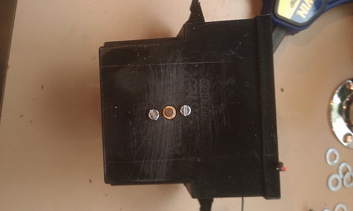
- Pick a surface on the box that is flat both inside and out and has room behind it, inside, for the motor to fit and center punch the spot where you would like the motor to be centered around.
- Before you drill a hole for the shaft, take a look at your motor/gearbox and check if there are any bosses at the base of the output shaft.
- Drill a hole at your punch mark.
- Drill clearance holes for the mounting screws.
- Place the motor's shaft through the center hole in the box and bolt it in place.
I chose to mount the Arduino board vertically on the back wall with the USB plug up, allowing easy future access. I knocked out one of the wire pass-throughs in the bottom of the box and fed the Bluetooth module through in an attempt to preserve as much range as possible. This box also holds the two batteries. I simply drop these into open spaces once they are attached later on.
Step 12: Final Assembly


Now that all the pieces of the puzzle are in place assembling the end product can be accomplished in three steps: wiring the potentiometer, attaching the screen to the rod, and assembling the housings and rod.
Wiring the Pot
Both the pot and the Arduino should have leads attached by this point, unfortunately it isn't as simple as connecting the two sets of leads. You need to make sure that when the screen goes up the pot is reading in the right direction and vice versa. To do this you need to decide which side the motor will be on when you face the screen. Then run the app and select either up or down and note which way the rod turns. At this point I used trial and error since there are only two possibilities and hooked the pot up to the Arduino using temporary connections. Now with the pot, NOT engaged in the rod, turned all the way to what should be the up position try running the screen up. It should ignore the command, if it does you are good to go, make the pot connections permanent. If it starts to run you need to simply switch the V+ and GND wires between the Arduino and pot. Do this and test again to make sure, then make the connection permanent.
You can also orient the motor and pot directions by modifying the Arduino sketch and the Android app but honestly it is much easier to swap the polarity on the pot.
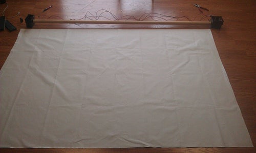
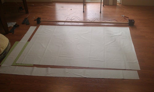
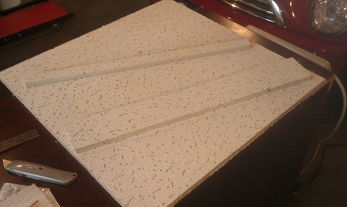
Attaching the Screen
My pictures show the rod attached to both the housings in a few of the pictures pertaining to attaching th screen, in hindsight it is easier if you remove the housings and just place the rod on the floor. Just make sure the motor shaft's flat is facing up and the set screw hole on the rod should facing up too.
Finding the width of the screen is easy, simply measure the available length of the rod, leaving .25"-.5" on each edge, mark the width, and cut.
For the height you need the correct length that keeps the screen in aspect (16:9) plus you need to compensate for the distance between where you want the top of the image and where the rod will sit. Longer is better because you can either cut some off the end or keep some rolled up in the next step, calibration.
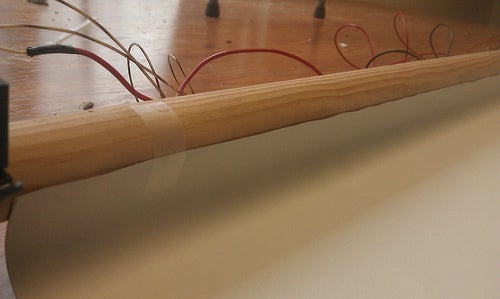
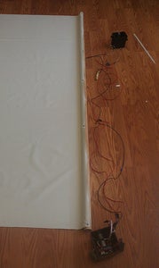
With the screen cut to size (and ironed if necessary) push the edge up to the rod so that it is in contact with the rod (check the pictures, they are probably clearer). When placing the screen you need to take into account which way the rod will be turning and which side of the material will be projected on. When everything's facing the right way and the screen is as square as possible to the rod, place small pieces of tape along the length to hold everything in place. Use an automatic center punch or knife to mark the place where the screws will go through the screen, near each edge and 6"-10" apart in between. Widen the holes in the screen by pushing the center punch through and then place a screw and small washer in each position. Once all the screws are in you may want to trim, or tape down, the edge of the screen that sticks out past the screws. It tends to stick out and then the screen doesn't roll up as cleanly.
Assembling the Pieces
This one is easy, I promise. Before you start, turn the potentiometer all the way to what will be the down position, then turn it back a 1/2 turn. Put the motor's shaft in the proper place, tighten the set screw (onto the shaft's flat if it has one), and press the potentiometer into the grommet on the opposite end.
Step 13: Calibration

- The pot should already be turned to the down position, 1/2 a turn from the stop, and the screen should be in the full down position. Set them in these positions now if they are not already. Also, attach both housings and prep everything to run.
- Lift everything off of the ground, either supporting the housings on something or getting someone to help you hold them, and press the up button on the app.
- When it is finished measure the amount of material left hanging of the rod. If it is an acceptable drop down distance then you are good to go, skip to the next slide.
- If to much is hanging down you have two options: trim some off of the bottom of the screen, if you have some excess, or adjust the upper threshold so you get more rotation. If you need even more you can adjust the lower threshold and then reset the pot and screen by hand.
- If the end of the screen wrapped around the rod extra times then you can bump up the lower threshold.
Step 14: Mounting


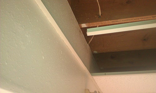


Preparing the Ceiling
- Pick a location for the screen. I don't have a lot of experience with drop ceilings but I feel like closer to a wall is better, less loss on integrity when you cut some of the supports.
- Remove the panels that fall within the width of your screen at the chose location.
- Mark the positions of and cut any supports that would interfere with the screen's deployment. I couldn't get the supports I needed to cut down without breaking them so I cut them while they were still in the ceiling. If you can get them down it is a lot easier.
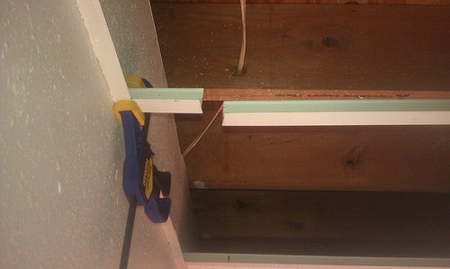
- Cut a couple of inches off of one side of each support ( the same side, this is critical). This leaves a gap in the supports where the screen can come through.
- Re-attach the supports. For me this meant using epoxy to attach a stub to the wall.
- Reinforce any of the cut supports that are longer than a few inches with hanger (plumbers) tape. Drill a hole in the vertical part of the support, screw the tape directly to the support or use a double hook, and attach the other end directly to a nearby joist. Check that when the support is weighted down it will hang at the right level.
- Hold one of the panels in place near a cut support and mark the gap size so the panels can be cut.
- Since the gap should be the same size and in the same location on all the panels, cut the marked panel and then use it to cut the rest of the panels. I used a box cutter to cut the panels. Two passes, the first to make a channel, the second cutting as deep as possible, followed by breaking the the panel along the edge of the bench. A down bend loosens everything then an up bend makes a pretty clean break.
You'll need at least one more pair of hands for this part. Also, test everything before you get to far and have to undo your work.
- Measure the distance between the two joists that the unit, housing to housing, is smaller than, that would allow the screen to be centered over the gap. For example, if your unit is 76" the joists need to be at least that far apart and they need to be at the edge of or outside of the gap you made in the ceiling.
- Use some scrap wood to build up the difference between the distance between the joists and the length of the unit.
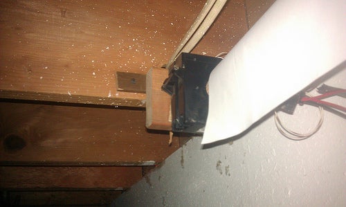
- With someone lifting the other end lift the screen into position and attach one of the build ups to a nearby joist. Mostly you are setting the height at this step. Try to get it as horizontal as possible but the rotational nature of the rod means you don't need to be super accurate.
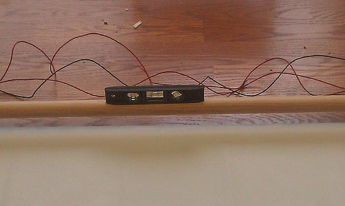
- With the first housing in place (have someone there in case the screen were to fall somehow) position the second housing and attach it's build up to it's joist. This will determine the final position of the screen so you need to use a level on the screen rod to check the height and make sure the rod is in position, parallel, over the gap in the ceiling.
- Test, test , test. You don't want to get everything put back in place to find you have a dead battery or loose connection.
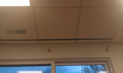
- Make sure everything is turned on and put the cut ceiling panels back in their proper place.
Step 15: Finishing Touches

This project has lots of room for expansion and improvement and I will probably be coming back to it in a while after we're more settled into the house. Some of my ideas are below.
Currently there is just a gap in the ceiling where the screen comes out but at some point I would like to develop a gate/door that blends into the ceiling better.
I also would like to experiment with different screens. While researching screens for this project I came across some people that claimed that a light gray screen will actually give better contrast. and I'd like to try it to see.
I envision an entire system controlled from one app where at the press of a button the screen deploys, lights dim, a projector deploys and starts, and hidden speakers are revealed. That's probably overkill for a system that I'll use 20 times a year but a guy can dream.
Back in reality all that's left is to dim the lights, fire up the projector, sit back, and relax. Thanks for reading!

Second Prize in the
Arduino Challenge

Participated in the
Woodworking Challenge

Participated in the
Make It Real Challenge


