

Introduction: Android DiceBot


If you are stuck on any step or have any questions, please post them in the comments section below.
I'm 11 years old, so I will be eligible for the 12 and under prize from the Robot Contest.
Step 1: Parts

All of the parts you can buy at SparkFun:
Relevant Parts:
ATmega328p $4.30
74HC595 Shift Register $1.50
7-Segment LED $1.95
An accelerometer (two axis or higher)
Android Figurine (this one should work, but I got mine in a bookstore in Japan Town, LA)
Perfboard
LiPo JST connector $1
LiPo - 110 mAh $7
Other Parts:
LED Red (2) $0.35
Arduino UNO $30
16MHz Crystal $1
22pf Capacitor (2) $0.35 Each
Resistor - 330 Ohm (3) $0.25 Each
LiPo Charger $10
USB-B Cable for your Arduino
A PC
Breadboard
Jumper Wires
Tools:
LOTS of thin wire
Safety googles and gloves
Dremel
Dremel Tips (Round and Conical)
Razor Blade or X-acto Knife
USB-B Cable for your Arduino
A PC
Breadboard
Jumper Wires
Soldering Iron + Solder
Note: In this picture, I don't have a spare 3-axis accelerometer.
Step 2: Dremeling


First, remove the head of the Android. This is not as easy as it may seem. The head of the Android is quite tight on the figurine that I have. A lot of pulling was required. After the head was removed, I Dremeled the top part of the head so that I wouldn’t have to pull hard to get the head out again. Next the eyes (the white dots) were Dremeled out so the LEDs could fit. A snug fit is good for the LED, but a bit of hot glue on the back side of the LEDs can help to hold them in place.
Now it is time to work on the body. The two areas to work with the Dremel are the neck and the body of the Android, where the 7-Segment LED will be. At the neck, most all of the plastic was removed so that the same thickness of the body of the figurine continued right to the edge at the neck (this makes it easier to fit more electronics in the body).
The front of the body is the last area to work on. I used the 7-segment display as an outline to mark the hole using an X-acto blade to gently outline the surface. I used the conical tip to make crisp corners and remove the rest of the plastic needed for the 7-segment display. Once I was near the X-atco cut guides, I worked slowly to ensure a snug fit. The fit ended up being snug enough that no hot glue was needed (good, because it would have been difficult to get hot glue in some of the areas in the small figurine)
Step 3: Loading the Code Onto the ATmega328p


Upload the latest version of ArduinoISP to your Arduino (found in the examples tab). Put your ATmega328p on the breadboard, then follow these instructions to program and bootload it:
Attach GND to GND and +5V to VCC on your Arduino and ATmega328p. Connect MISO, MOSI, and SCK pins on the Arduino and the breadboard together (pin 17 to D11, pin 18 to D12, and pin 19 to D11). Connect the RST pin of your Quasi-duino (pin 1) to D10 on the Arduino. MAKE SURE to insert the 10uf electrolytic capacitor between RST and GND on Arduino (the long lead goes to RST). If you would like, connect one LED to D13 on your Quasi-duino and the other between VCC and GND to debug.
Then download the zip at the bottom of this page (Quasi-duino.zip) and put it in your hardware folder (if you do not have one, name a folder "hardware" and put it in your sketch folder). Click out of the Arduino IDE. Then click back into the Arduino IDE. Now, in the boards selection, you should see "Quasi-duino (8MHz internal clock)." This is the 8MHz internal clock selection of the ATmega328p. Now, put in your crystal from X1 to X2 (pins 9 and 10). Put your 22pf capacitors in, one between X1 and GND, and the other between X2 and GND. Select the Quasi-duino in the boards menu and burn the bootloader w/ ArduinoISP. After about a minute, you should see "Done Burning Bootloader".
In your current Arduino, most of them will have a 16MHz external clock (the oblong shape shiny silver thing that says SPK16.000G). You might ask, "why the extra components, it's just an extra cost." Well, the internal clock is not as accurate, just a few microseconds off. If you were programming for a drone or just using serial communication, you will want an external crystal (the clock) for more accuracy. In most of your regular projects, you will find that most do not require an external crystal.
Other electronics components you may not need (not included in the ATmega328p) are: a voltage regulator (for more voltage being able to come into your ATmega328p), LEDs (but you might want to check if it gets power once in a while, but it takes about 35mA of power to run continuously), or even your USB interface. Once you program your chip for the project, you could take off the USB interface, taking off about 15uA.
I have modified the current breadboard Arduino core for this project. Now, the Quasi-duino can compile code, and upload with ArduinoISP. Previously, this was not possible with the current cores available on the Arduino site. The code at the bottom of this page is the modified Arduino core that works with the Quasi-duino.
Download the zip file of the file/library named "Pineapple." My library will help to decrease 1.5 pages of code down to a few lines. This is my library for the 7-Segment and the 74HC595 shift register. To use this library, put it in your Arduino's libraries folder.
Download AndroidDicebot.ino at the bottom of this page, and double-click the fie once downloaded. Load the code onto the ATmega328p by pressing File > Upload Using Programmer.
After that, take out the ATmega328p for the next step.

Step 4: Cutting the Perfboard


Get out the perfboard, and put your safety goggles and gloves on. Make sure that you are in a well ventilated area. Solder the 74HC595 into the perfboard, with two hole guard room from anything else on any side. Solder the programmed ATmega328p into the perfboard with two hole guard room from anything else on any side (if you are soldering the ATmega328p right next to the 74HC595, make sure to leave three hole guard room from the 74HC595).
Cut the perfboard with the razor blade or X-acto so that the ATmega328p and the 74HC595 have one hole guard room between the chip and the end of the perfboard. You may experience difficulty in cutting this because perfboard is very hard to break. The easiest way to do this is to make deep cuts through the spots described above on both the top side and the bottom side. Then, on the edge of your workbench, put the place where you are going to cut on the tip of the edge of your workbench. Then push VERY HARD and see if it breaks. If it doesn't work, try and cut deeper into the perfboard.
Note: In the pictures, I have a DIP socket instead of an ATmega328p.
Step 5: Soldering


WAIT!!! Keep your gloves and safety glasses on. Perfboard is made of fiberglass, so MAKE SURE to wear gloves.
Follow the Fritzing diagram above, and solder away!!!!!!!
Now, bend and twist all of the wires, fit all of the boards in, and then put the LEDs into the eyes (the ones that you Dremeled out).
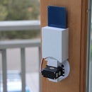
Step 6: Your New Android Dice!!!!!!!
Now you should have a fully functional Android Dice! If you have any questions, please leave them in the comments section below.

Participated in the
Robot Challenge


