

Introduction: Android PfodApp Controlled Datalogging Arduino IRTemp Meter


Introduction
This instructable shows you how to make an Arduino based IR temperature meter that is controlled by your Android mobile. It uses pfodApp to do the control. No Android programming is required. You can customize the functions provided by changing the Arduino code.
The webpage pfodIRTemp breaks this project down into 3 stages. Starting from a simple datalogger of the IR temp and working upto the menu driven project shown here. This instructable will go straight to stage 3,
Note: Revision 15 of pfodApp (available from the market places) fixes a problem with saving the data to a file on your mobile
Cost
Cost is about $115 + shipping (including the teflon wire and a wire stripper but excluding a soldering iron and other tools)
Construction time is <1hr
Features
A menu driven Android controlled IR temperature meter which can
i) Display the IR Temp reading
ii) Switch between Celcius and Farenheit
iii) Log the readings with their time in csv format for later uploading to a computer
iv) Display an averaged IR reading
v) Let the user select the number of readings to be averaged.
vi) Adding a 9V battery pack, as described here, makes this a remote stand alone IR Meter
Specifications
The basic IR Temp Sensor has these specifications
Measurement temperature: -33 to +220 °C
Accuracy at read temp 15~35°C / ambient 25°C: +/-0.6°C
Full range accuracy: +/-2%, 2°C
Resolution: 0.0625°C (full range)
Response time (90%): 1 second
Distance:Spot ratio: 1:1
Emissivity: 0.01~1 step 0.01
Update frequency: 1.4Hz
Wave length: 5um-14um
Uses
I built this project to measure the temperature of individual ICs on a power switcher I was building. There are inexpensive IR temperature meters available but this one can be modified to suit your purpose and also logs the readings for later processing and plotting. Also since this IR meter uses a bluetooth connection, adding a battery lets you position the IR sensor remotely so you can monitor your experiment from a safe distance.
Quick Start
1) Buy the parts in this list . freetronics will ship the IR Temp sensor overseas (outside Australia)
2) Install the Arduino IDE from http://arduino.cc/en/Guide/HomePage
3) Download the pfodIRTemp.zip and pfodParser libraries and unzip them to your Arduino library directory.
(Open the Arduino IDE File->preferences window to see where your local Arduino directory is).
4) Connect the Arduino Uno with the USB cable and open File-> Examples -> pfodIRTemp -> pfodUnoIRTempMenus sketch and load it into your Uno.
5) Set the switches on the Bluetooth shield. Set the 3V/5V switch to 5V and set the To Board/To FT232 switch to the To Board position and plug into the Uno. Make sure the pins all line up correctly
6) Wire up the IR Temp sensor to the prototype shield as shown on IRTEMP Infra-Red Temperature Sensor Quickstart Guide and plug the prototype shield into the Bluetooth shield.
7) Download the pfodApp to your Android mobile. This app can be used to control all your pfodDevices
8) Pair your mobile with the Bluetooth shield and setup a pfod connection called IR Temp Sensor, as described in pfodAppForAndroidGettingStarted.pdf.
9) Start pfodApp on your mobile and choose the IR Temp Sensor.
10) Add a 9V battery, as described here, to make this a portable remote IR meter.
Finished.
To upload your saved temperature readings to your computer see the instructions in pfodAppForAndroidGettingStarted.pdf.
The rest of this Instructable will describe how IR Temp Sensor is mounted and wired to the prototype shield.
Step 1: Wiring and Mounting the IR Temp Sensor


Wiring the IR Temp Sensor
The only bit of wiring needed for this instructable is to wire up the IR Temp sensor to the prototype shield.
For the sensor wires, 26 AWG Teflon insulated wires provides a very tough and heat resistant connection. (See the parts list for a source of Teflon wire.) Teflon insulated wire is very hard to strip without cutting the strands of wires. The recommended method is to use a wire stripper, like the one listed in the parts list and close the wire stripper on the wire then open and remove the wire stripper and pull the cut insulation off by hand. Using the wire stripper to pull off the insulation tends to cut the wire.
The IR Temperature Sensor wiring is straight forward. There are 5 wires that need to be connected. (see IRTEMP Infra-Red Temperature Sensor Quickstart Guide)
V (VCC) connected to Arduino 5V.
G (GND) connected to Arduino GND.
D (Data) connected to Arduino digital pin D2.
C (Clock) connected to Arduino digital pin D3.
A (Acquire) connected to Arduino digital pin D4.
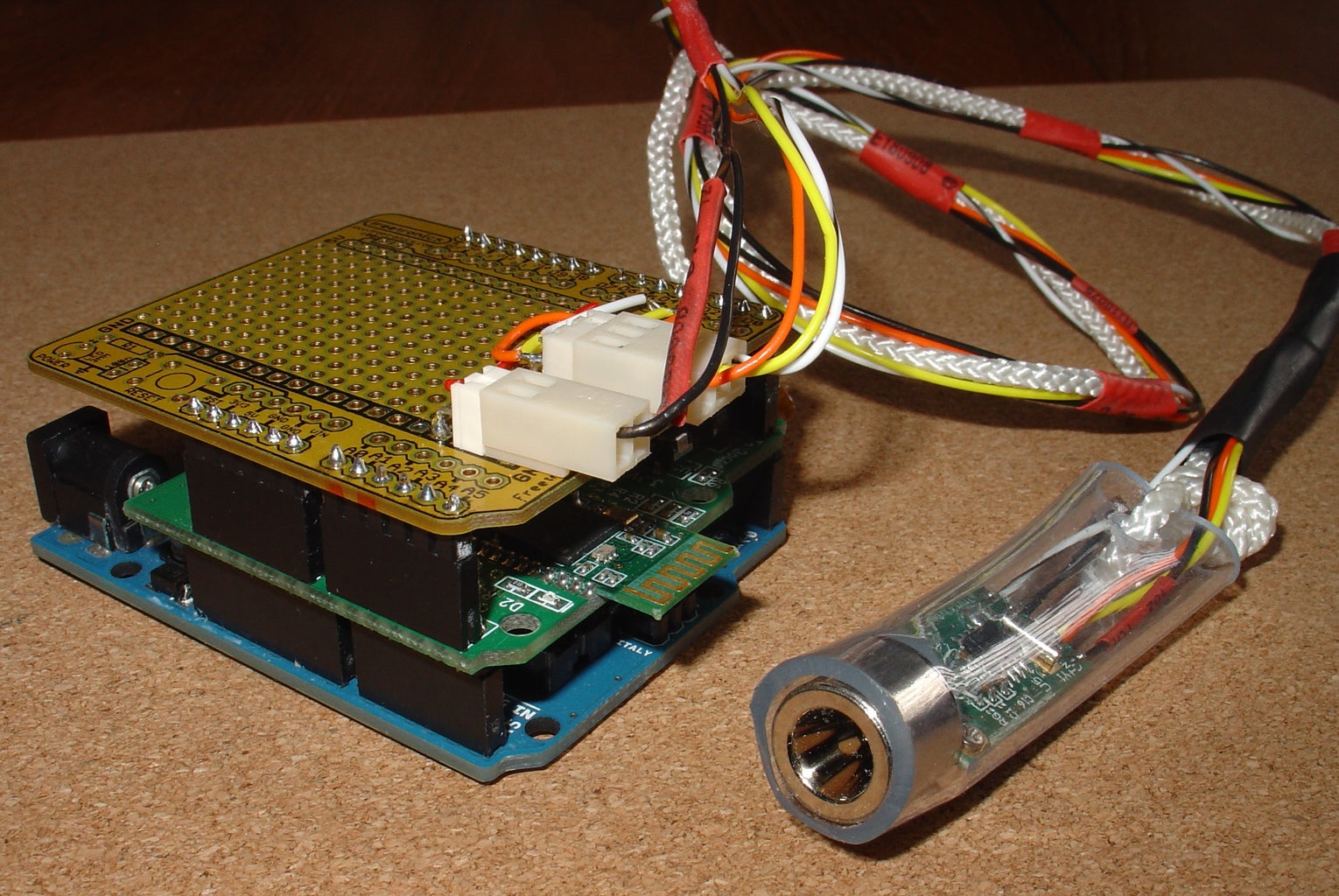
The photo of the prototype shield shows this wiring using push on connectors. You could just wire direct to the shield if you wished.
Mounting the IR Temp Sensor
As shown in the photo, half inch internal diameter clear plastic tubing pushed over the sensor makes a suitable mounting. (Note: Do the wiring first, the tubing does not come off once pushed on.),
A nylon cord attached to the plastic tubing, provides strain relief for the wires and should be secured at the prototype shield to prevent the wires being pulled.
Step 2: The Arduino Code


The Arduino code for pfodUnoIRTempMenus.ino is included as one of the examples in the pfodIRTemp.zip library. As well as the pfodIRTemp library you will need to download and install the pfodParser library.
The image shows how simple the command parser code is. Each command the Android pfodApp sends to the Arduino pfodDevice is a single letter. The parser.parse(in) returns 0 until a complete pfod message is received, e.g {s} When the closing } is received the parser returns the first byte of the command, in this case 's' The code then acts on that command. See the pfod Specification for details and examples of the messages available.
Most of the commands used in this instructable don't have any arguments. However one command, the one that sets the number of readings to be averaged does return one argument, the index of the item the user selected.
When the user clicks on "Set the number of reading to be averaged", the Android pfodApp sends the command associated with this menu item (the pfodDevice in a previous message told the pfodApp what commands went with what menu text). In this case the pfodApp sends {n} The pfodApp does not know what that command means or what will happen next it just waits for the Arduino pfodDevice to respond. The code in your Uno see the 'n' command and sends back the message to tell the pfodApp to display a single selection list with a particular set of choices (see the screen shot) The message sent was
{?m`2~Set number of samples to be averaged|Average 2 Readings|Average 4 Readings|Average 8 Readings|Average 16 Readings|Average 32 Readings}
The ? tell the pfodApp this is a single selection screen and the m is the command that needs to be sent back with the users selection. The 2 is the current selection, the third item counting from 0 and the rest of the command are the text descriptions for the choices separated by |
When the user selects a choice and clicks on the send button the pfodApp sends back the command and the index of the choice.
For example the return might be {m|4} if the user selected the 5th time (the index starts at 0).
The lines of code
} else if (cmd == (byte)'m') {
byte* idxPtr = parser.getFirstArg(); // parse 1 arg as a number
long longResult;
parser.parseLong(idxPtr,&longResult); // only one arg
extract the index return with the 'm' command. This index is then used to set the number of reading to average.
As you can see it is easy to modify the menus and choices presented to the users. They are all controlled by the Arduino code. No changes to the pfodApp Android code are necessary.
For other projects controlled by the same pfodApp see www.pfod.com.au

Participated in the
Build My Lab Contest


