

Introduction: Anniversary Cabinet With a Wooden Combination Lock


The cabinet was made as a wedding gift for my son and daughter in law. The cabinet itself follows conventional design and construction techniques - what makes the anniversary cabinet different is the combination locking mechanism. The four drawers require you to know a code (combination) in order to open them. Each drawer has a different combination. The idea then, is to give the combination for one drawer at a time (on the wedding anniversary). To get things going though the combination for the first drawer (the bottom one) is given "free" at the time the gift is presented so that the general operation can be explained and tested. In this case the guests at the wedding reception were given a sheet of paper and an envelope so that they could write a note to the bride and groom. The envelopes were sealed and placed at random in the top three drawers. So on the anniversary when the combination is revealed the contents (envelopes or other gifts) can be accessed. Of course this may not work as intended, as the level of bribery re getting the combination early could come into play.
The video below shows how the combination locking system works and the Steps following the video give details on the construction of the cabinet and the locking system.
Step 1: Video Showing How the Combination Locking System Works on the Anniversary Cabinet
Step 2: Some Stages of Cabinet Construction


Mortise and tenon joints, pocket holes, and dovetails are the primary joinery methods used in the construction of the cabinet and drawers. But any kind of joinery can be used to make a cabinet/drawer for the purposes of including a combination lock like the one described in this instructable.
Step 3: Making the Lock Rod Plates


Each drawer has a "lock rod plate" that mounts with two screws to the drawer. The drill press and the table saw (with a sled) make this operation easy. I used scrap wood spacers to keep the spacing between openings consistent.
Step 4: Making the Lock Rods
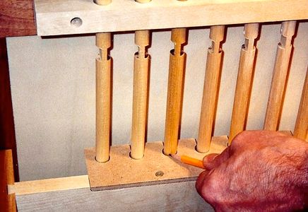


Mark the dowels where you need the flats machined after the lock rod plates are made and mounted on the drawers. The flats on the lock rods (1/2 inch dowels) are made with the router. An mdf block with a setscrew secures the rod for the first flat as the block runs in the router table groove. Flipping the block over and routing the second flat ensures a perfectly parallel set of flats. A little bit of sanding at the cuts completes the procedure. Seven lock rods were needed for this cabinet. The angular position of the flats for any given lock rod were selected arbitrarily - I just mixed it up a little by eye. Light springs and brass pins keep the rods in place and makes for smooth turning.
The combination of the lock rods and the lock rod plates on the drawers should, in theory, complete the locking system and present so many combinations that guessing the correct one (or two) would be pretty well impossible. However, I should mention that this is Generation 2 of this wooden combination locking system. The first cabinet had pretty well an identical system to this one in terms of the lock rods and the lock rod plates - but it didn't take long for son number one to figure out how to beat the system. By applying a light tugging pressure on the drawer handle as you slowly twist each lock rod, you can eventually "feel" as each of the rod flats line up with the lock rod plate openings. To overcome this deficiency in the current version of the cabinet, a hinged "lock rod cover" with a linkage to a pins that fit in a right angle groove on both sides of each drawer securely locks the drawer in place when the lock rod cover is open. With this setup you can't twist the rods and tug on the drawer to beat the system because when you can see the rods to twist them (cover Open) the drawers are locked in place by the pins. The video above or here: http://youtu.be/jXR1rI32I5A makes this easier to understand.
Step 5: Lock Rod Cover and Linkage Details


I put together a couple of mock-ups as part of the design process to get the lock rod cover and the linkage working smoothly before i did the final construction. One mock-up is shown here. I went with plastic flat bars to give a friction free sliding action and to insure dimensional stability in the system over time. The brass pins that are press fitted into the plastic flat bars are kitchen cabinet shelf pins.
Step 6: Some Other Details and a Question


The lock rod brass "pointers" are made from one-half of 1/2 inch brass grommets (the kind used for sails, tents, etc.). The points of the compass are the heads of brass brads. The final step to make the locking system work even more effectively is the lock rod shield plate that is shown being inserted in the drawer cavity. This shield helps prevent visual observation of the lock rod positions when one or more drawers are removed.
I'm hoping that some Instructable viewer can figure out how many lock rod combinations are possible, besides the correct one (or two), for any given drawer. (I don't know)

First Prize in the
Woodworking Challenge

Participated in the
Spy Challenge


