

Introduction: AquaFeeder 2.0: Automatic Fish Feeder (with WiFi)


Looking after two aquariums isn't an easy job, especially for someone as forgetful as me. Sometimes, I'd forget to feed the fishies for several days until my mom would notice floating fish skeletons. Well, nowadays that never happens, because of the new AquaFeeder2.0 - a machine that feeds the fishes all by itself!
Yes, AquaFeeder is fully automated; all you have to do is leave it on 24/7, and it will automatically feed the fish twice a day. It does everything on its own, from opening and closing the aquarium lid, to dropping fish food. It also keeps you updated with the details of the aquarium and itself through a webpage that can be accessed by any phone, tablet or computer on your WiFi network.
AquaFeeder is a great machine that you could use if:
- You are forgetful (like me)
- You are busy and working all the time (like me)
- You are on vacation and need to feed the fish when you aren't there.
- You want the best care for your fishes.
- You like making stuff instead of buying them (yeah, the true maker spirit \m/)
This isn't actually my first ever automated fish feeder; I made AquaFeeder1.0 about 6 months ago (check out its instructable too!). Unfortunately, AquaFeeder 1.0 desperately needed a serious upgrade. You couldn't really be sure if it actually fed the fish at a particular time or it failed to do so. It also needed some user interface which could allow someone to access it remotely.
AquaFeeder2.0 took care of those problems; it is equipped with the (incredibly powerful) Intel Edison, it now has inbuilt WiFi and Bluetooth and compatibility with several programming languages that unleashes a huge number of possibilities. Here are some of AquaFeeder 2.0's new features:
- WiFi connectivity: Get data from AquaFeeder or control it through a webpage.
- Email notifications: Sends you an email when it successfully feeds the fish.
- WiFi synced time.
With these features along with a better CPU and program, AquaFeeder is now closer to being a commercial product than a prototype.
The bottom line: AquaFeeder2.0 is a vastly improved automated fish feeder that regularly feeds the fish all by itself, while using the sophisticated features of the Intel Edison to keep the user up to date with info about the aquarium and fish.
Wanna see how exactly AquaFeeder works? Keep reading below!
Step 1: How AquaFeeder Works...

AquaFeeder's main job, simply put, is to feed the fish. For a machine, this actually isn't as simple as it sounds.
How does AquaFeeder2.0 feed the fish?
AquaFeeder has 2 user-set feeding times, which means it feeds the fishes twice a day. Whenever it's time to feed, one servo motor opens the aquarium lid, another servo drops the fish food into the water, and then the lid is closed again.
 AquaFeeder first opens the lid
 - Then the fish food is dropped into the water.
- The lid is closed after feeding.
 AquaFeeder first opens the lid
  Then the fish food is dropped into the water.
  The lid is closed after feeding.
Video: This video shows how AquaFeeder feeds the fish using its servo motors.
The LCD display:
When not feeding the fish, AquaFeeder's LCD displays the web synced time and it's IP address. The time to feed next and the previous time fed are also figured out and displayed on the LCD display for the user's convenience.

OTHER FEATURES:-
WiFi and Webpage:
Using your browser (like Google Chrome or Safari), you can access AquaFeeder through a webpage. On this webpage, you can view details, such as the time to feed the fish next, the time previously fed etc. You can also set custom feeding times or tell AquaFeeder to feed the fish right now.
Web Synced Time:
The Edison obtains the current time from the NTP server (one of the many official time servers where computers and other IoT devices sync their time with). This is very convenient as you don't have to keep setting the time manually. This picture below gives a brief of how the Edison synchronises the time with the Internet using NTP (network time protocol).

As shown above, the lcd displays the time and IP address.
Step 2: About AquaFeeder 2.0

What's new in AquaFeeder 2.0?
- Better automation: AquaFeeder 1.0 was an automated machine, but there were many problems. For example, 1 out of 8 times the feeding program would fail and the fish wouldn't be fed, maybe due to power loss or unusual behaviour of the servo motor. Also, it couldn't figure out if it had missed feeding the fish, or if it was off during the feeding time.
AquaFeeder 2.0 has a better feeding algorithm that wouldn't let the servo motor take too large amounts of current. Even if it fails feeding completely due to a power failure, when it is switched on again, the program will feed the fish immediately after booting up.
- Easier To Use: AquaFeeder 2.0 has a simple alphanumeric LCD screen (instead of a graphic LCD) which displays all important information at one glance. In the picture below AquaFeeder's LCD is showing the next time to feed and the time previously fed. Every few seconds the LCD displays different information.
There are no buttons to fiddle around with. AquaFeeder is entirely controlled through the webpage on the local WiFi network, so anyone can access it from any place in the house on any device with considerable ease.
- Better lid opening mechanism: Now much more sturdy, without the mess of double tape.
- Powerful On-board Computer: The Intel Edison doesn't just run Arduino code, but can also run python, C, and nodejs. In English, it simply means that it's MUCH more powerful and sophisticated than AquaFeeder1.0.
- Control AquaFeeder from any device, anywhere! - You can view details and set feeding times for AquaFeeder through a webpage on the local WiFi network!
- See the tags on the images above to see the differences between AquaFeeder 1.0 and 2.0 side by side.

Step 3: Project Materials and Details...


Time Required: 2 weekends, if you work fast enough
Cost: ~$120-$130 (including the Edison Arduino breakout board)
Difficulty: Hard (9/10)
Skills Required:
- Programming with Arduino (and general programming know-how)
- Using Linux Command Line (even a little experience is sufficient)
- Electronics
- Making stuff out of paper and cardboard (strong sturdy stuff, not art and craft)
Materials For Electronics:
- Intel Edison Arduino Breakout Board
- 1 standard servo motor
- 1 micro servo motor
- 16x2 alphanumeric LCD screen
- Breadboard shield
- 2N2222 transistors (2)
- Buzzer
- Jumper wire
- WiFi antenna (optional)
Materials for Stand:
- Mountboard (white cardboard)
- Firm double layer cardboard
- Ice cream sticks
- PVA glue
- Superglue
- Small nail
- Double Tape
- 2 part adhesive (like Araldite or Bondtite)
Step 4: Designing the Fish Feeder Stand...

What's this "Fish Feeder Stand" and why do we need it?
The fish feeder stand holds the standard servo motor just above the aquarium's lid. The servo motor on this stand will drop the fish food into the aquarium after the other (micro) servo opens the aquarium's lid. Depending of the design of the tank, you may even attach the "feeding" servo directly to the lid of your aquarium.
The fish feeder stand I made comprises of the following parts:
- The "Tower": This is the vertical column, labeled "1" in the picture above.
- The Servo Holder or "Jib": Labeled "2" in the above picture, the servo holder will be the part that holds the feeding servo (that holds the fish food) above the tank's lid. I call it the "jib" because it's similar to the corresponding part of a crane.
- The Base: Supports everything.
All these parts have been made with cardboard and ice-cream sticks (for rigidity). Of course wood or 3D printing may be a better option. but I have no experience in either of them.
When you are designing the fish feeder stand here are a few things you must keep in mind:
- The "tower" must be at least 3 inches higher than the aquarium lid.
- The feeding servo must be place in such a way that it doesn't hinder the opening and closing of the aquarium lid.
- The base should have a large surface area and must be firm.
- The tower, "jib" and base must be rigid and sturdy.
I'd recommend first roughly drawing a plan of a fish feeder stand like I did (in the pic above) and then commencing to the next step...
Step 5: Making the Stand's "Tower"...


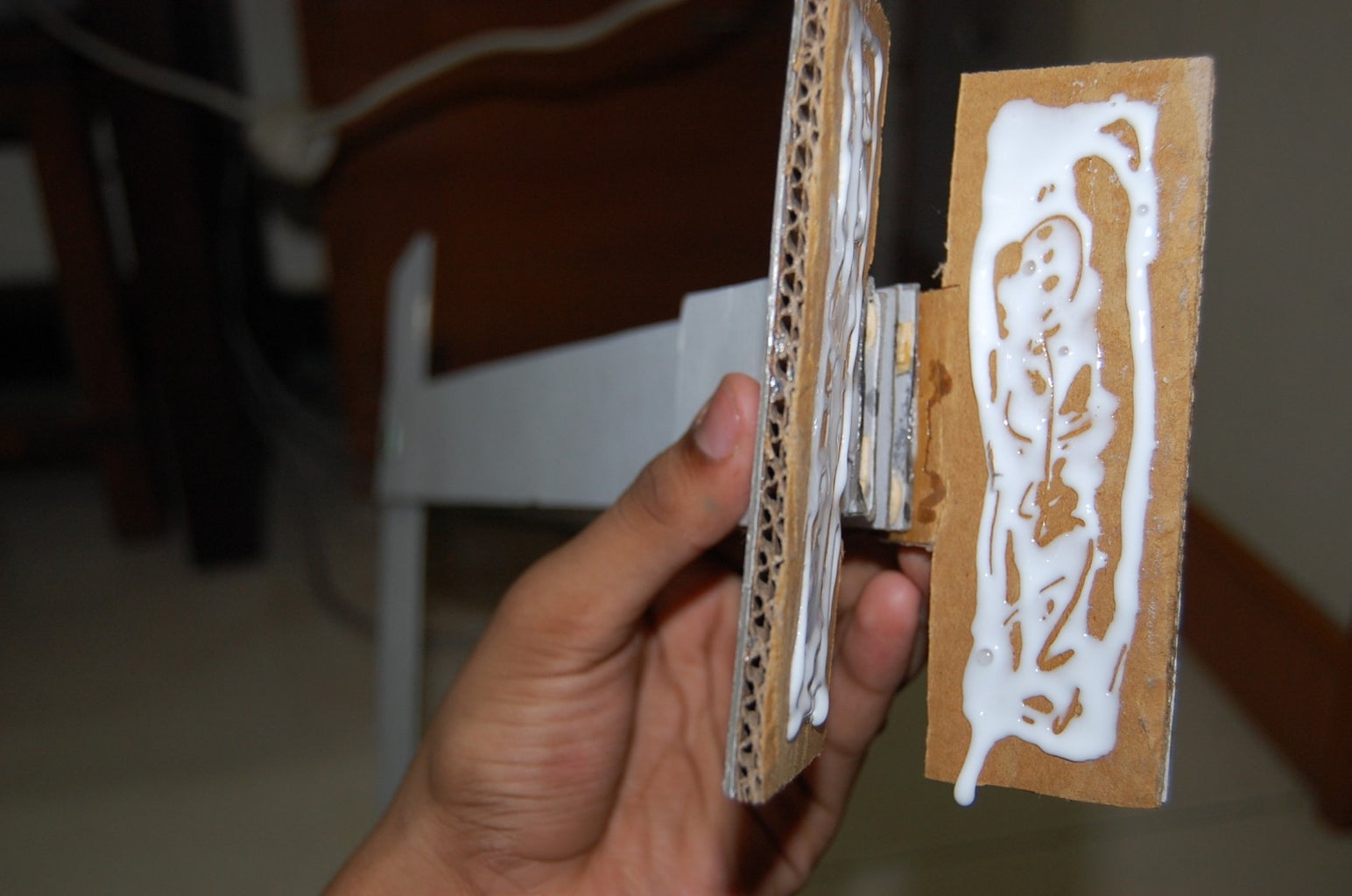
Each column of the "tower" is made of two mountboards stuck together with ice-cream sticks in between (for rigidity). There are 2 such columns.To make 1 column:
- Cut out a 2 pieces of mountboard about 1.5 inches in breadth and 3 inches longer thn the height of your aquarium.
- Then stick ice-cream sticks onto one piece of this mountboard in the pattern show by the 3rd picture above.
- Now put some glue on these ice-cream sticks (as shown in the 4th picture), and stick other piece of mountboard to complete one column.
Make two such "columns" for the tower, and then continue to the next step...
Step 6: Making the Stand's Base Support...


The base support attaches the tower the the stand's base. To make them:
- Cut out 2 T-shape pieces of mountboard (with the dimensions shown in the 1st picture above) and 2 identical pieces from some firm double-layered cardboard.
- Stick the T shaped mountboard and firm cardboard together, such that they overlap each other. Do the same to the other pieces of mountboard and cardboard.
- With a cutter make a slight incision on each T-shaped support. See the 4th picture above for help.
- Bend each T-shape piece by 90 degrees.
- Now stick each T-shaped base support to each column of the tower we made earlier. See the 5th image above...
Step 7: Making the Servo Motor Holder (or Jib)


The jib will hold the feeding servo motor directly above the aquarium lid. To make the jib:
- Cut out 2 pieces of mountboard 1.5 inches in breadth. Their length should be at least 5 inches more than the distance between your aquarium lid's opening and the lid's edge.
- Just like in step 3, sandwich the ice-cream sticks between the two pieces of mountboard with PVA glue to finish the jib...
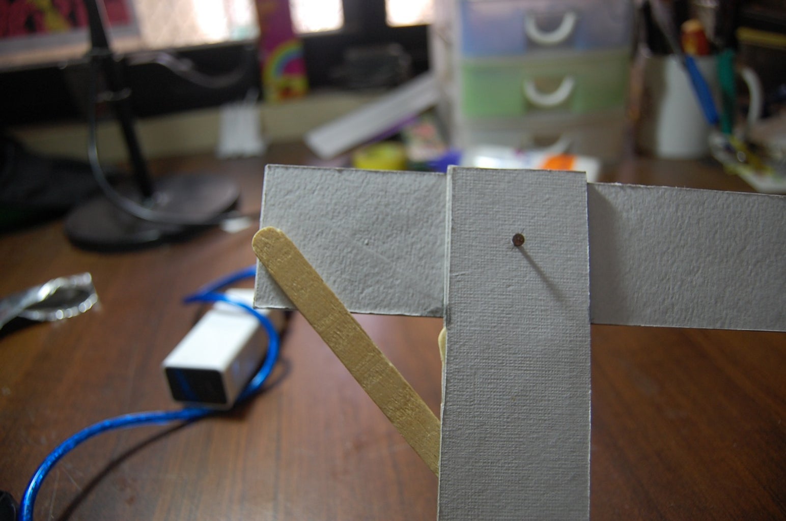
Before attaching the jib to the tower, stick some pieces of ice-cream sticks on one column (of the tower) as shown in the 3rd picture above. The idea is that when we stick the two columns of the tower together, there should be a gap in between to fit in the jib.
To attach the jib to the tower:
- Insert the jib into the gap between the two columns of the tower.
- You should leave at least 2 inches of the jib to the left of the tower, as shown in the 4th picture above.
- Now insert a nail to hold the jib to the tower. The jib will be able to rotate around the nail, so you can adjust the angle between the tower and jib later.
Step 8: Attaching the Stand's Tower to the Base...


Now we've got to attach the Tower to the base. To do that, follow these instructions:
- Cut out a piece of firm double-layered cardboard about 5 x 5 inches in dimensions.
- Put some PVA glue on the base support attached to the stand's tower, as shown in picture 1.
- Stick the stand's tower to the firm cardboard base (as shown in picture 2). Keep a weight to hold it in place until the glue dries up completely..
You can also use some super glue to secure the bond.
Step 9: Finishing the Stand...

We now have to adjust the angle between the stand's "jib" and the tower. Place your stand next to the aquarium as shown in picture 1. Adjust the angle between the jib and tower, such that the jib doesn't come in the way when opening or closing the aquarium's lid. Then fix the jib's angle permanently using some PVA glue and ice-cream sticks, as shown in picture 2 above...
Step 10: Attaching the Feeding Servo Motor...

Now its time to fix the servo motor onto your fish feeder stand. I attach a standard Radioshack servo motor to the end of the "jib" of my fish feeder stand with the help of double tape and rubber bands. Now attach the fish food container to this servo with some rubber bands.
Step 11: Attach the Servo to the Lid...


Attach a strong piece of string to the Micro Servo Motor and fix it just behind the lid's hinge (as shown above). I've used super strong 2 part adhesive which is way cleaner than nasty doubletape. After the glue dries, stick the other end of the string to the lid (see 1st picture) with a combination of insulation tape and super strong adhesive (see picture 3).
Step 12: Prepare the Intel Edison...
Prerequisites: Before continuing with this project, you should have done the following for thee Edison:
- Installed all drivers on the computer
- Installed the Arduino IDE
- Flashed linux image onto the Edison.
- Established a serial connection with the Edison and connected it to WiFi
- Downloaded Putty and WinSCP
After following these basic getting started instructions, be sure to follow the following steps if you haven't already:
- Open a serial connection with the Edison using Putty.
- Enter this command: vi /etc/opkg/base-feeds.conf
- Now type in:
src/gz all http://repo.opkg.net/edison/repo/all
src/gz edison http://repo.opkg.net/edison/repo/all
src/gz core2-32 http://repo.opkg.net/edison/repo/all
- Now hit the escape key and type :wq
- Type in opkg update.
- Yay thats done! You can install many programs, like nano (a much more user friendly test editor that vi). Just run opkg install nano and it should download and install on its own.
This page helped me with getting these instructions.
Step 13: Prepare the LCD Screen...


I simply connected a bunch of jumper wires to the required pins of the LCD screen. On the other ends of the wires I soldered on make headers (see pic above) so that they'd easily connect to the headers on the Edison breakout board). Note: Be sure to mark which wire is which in order to avoid confusion later on!
Wires to be connected to Edison: D4, D5, D6, D7, RS, E (aka enable pin) [leave one end of these unconnected for now!]
Other connections:
- R/W pin to ground.
- 1K resistor resistor between VEE (also labeled V0 sometimes) and ground
- LED+ to +5V through 220ohm resistor
- LED- to ground.
Step 14: The Circuit...


Now to the fun part - the circuit.
The circuit consists of:
- 2 Transistors, controlling the servo motors' signal
- A buzzer.
- An alphanumeric LCD screen (the green made-in-china ones)
I've arranged my circuit on a home-made breadboard shield, though you use a plain old half breadboard from SparkFun. Follow the pictures above to make the circuit...
Note that the motors only have to be connected later on...
Step 15: Arduino Code + Some More Programming...

The Arduino code is long. 800+ lines of code for me is flabbergasting! Anyway, the zipped folder is available below. Simply download it, unzip it and open it with the Arduino IDE. Before uploading to the Edison, follow these instructions:
- Open a connection to the Edison using WinSCP.
- Right click and create a file named "arduino"
- In the file, enter this - 12,30,0,19,0,0,22,51,22,19,0,0,6,0,0
- Now save this file.
- Make another file called "text.htm" and insert the text from the file below called "text.htm":
Also, go the the line beforevoid setup() where the WiFi ssid and password have been declared.
<p>//WiFI variables<br>int status = WL_IDLE_STATUS;
char ssid[] = "your network name";        //your network SSID (name)
char pass[] = "your*network*pass****";       // your network password
WiFiServer server(88);</p>
Changed these according to your network, and then upload the Arduino sketch to the Edison. Go on to the next step to test AquaFeeder!
Attachments

Step 16: How the Arduino Code Works...

Most of you wouldn't want to go through the entire code to try and figure out how it works and where each section of code, especially because there are 800+ lines of code (a LOT for a noob like me). So here is a brief of the execution of the Arduino code of AquaFeeder2.0:
void setup(){ //the setup part is run only once, immediately after the program begins
- Begin serial connection at 115200 baud
- Begin LCD and show AquaFeeder2.0 splash screen
- Attempt to connect to WiFi network
- Begin a server on port 88
- Show details of WiFi on LCD and Serial port
- Obtain web time using NTP
- Get variables like feeding times, previous time fed etc. from "arduino" text file under /home/root/ on the Edison.
- Check if any feeding time has been missed, and if it has, then start feeding the fish
- Figure out the time to feed next
- Set servo motors to their initial position
}
void loop(){ //the loop runs over and over again after the setup()
- Listen for web clients (meaning, be ready to create a webpage when someone requests it from a browser on their computer
- Display different information on the lcd alternatively; Current time and IP address, then next time to feed and previous time fed every few seconds
- Attempt to get web synced time if it failed to do so
- Compare current time and feeding times and determine if it is time to feed the fish
- If it is time to feed the fish, carry out the feeding the fish with the function feedfish();
}
void feedfish(){ //A function which includes all activities carried out when time to feed
- Create a sound with the buzzer
- Show "Opening Lid" on LCD and start opening lid using servo motor on pin 3
- Rotate the feeding servo (connected to pin 2) halfway to shake the fish food container so that fish food falls into the water
- Rotate the feeding servo motor back into the initial position
- Use the lid servo to close the lid
- Update previously fed and next to feed times
- Send email with necessary information
- Update the file "arduino" under /home/root/ on the Edison
Step 17: Testing Edison (without Attaching Motors... Yet)
Checking if LCD works and Edison connects to WiFi:
Open the serial port on the Arduino IDE. After the sketch uploads, you should see the LCD display show "AquaFeeder" along with a loading sign. After that it would attempt to connect to your WiFi network (so be sure that your router is always on!). If it connects successfully, the LCD would display the Edison's IP address, while the serial port will show other WiFi details like signal strength.
Checking if Edison successfully gets web synced time and obtains variables from "arduino" text file.
Now, the Edison will make an attempt to get the time from the NTP server. If it does successfully, it will send the current time to the Serial port and display it on the LCD. The Edison will then open the "arduino" file (which we made earlier) and read the number variables off it, then determine the feeding times, previous time fed, previous day fed etc.
After all this happens, the Edison will go through the main loop(); the LCD will switch through showing the current time and IP address or next time to feed and previous time fed every few seconds. On the serial you should see the message "Listening to clients". This refers to the Edison's webpage.
Testing Edison's webpage:
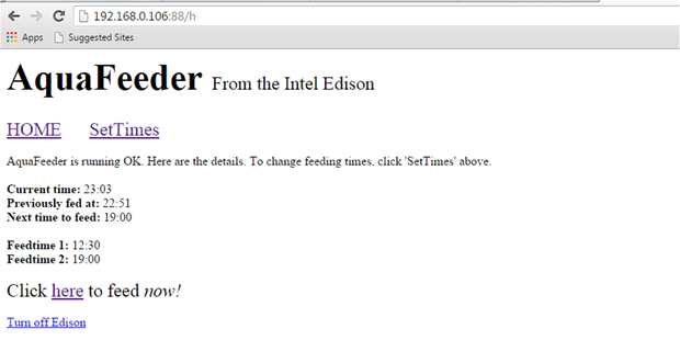
Now, on your computer, type in :88/h. For example if the Edison's IP address is 192.168.1.12, type in 192.168.1.12:88/h. Look at the Serial port now. You should see the message "GOT CLIENT!" and some other messages after that. On your browser, you should see a webpage load that looks like this:
Step 18: Making an Enclosure...


I'm lazy, unimaginative, out-of-time and lack a 3D printer, so I had to end up with an enclosure made from the box the Intel Edison came in. Well at least the box looks better than the origami box I tried making earlier (which failed MISERABLY), and I can still use it to store my Edison if I like.
How you cut up your box is up to you; just keep in mind that the headers should be accessible and preferably the USB and DC connectors too.
Step 19: Connect the Servos...


It's time to move the AquaFeeder stand to the aquarium! I had to extend the servo wires so that it could reach the Edison that was placed at the base of the stand.
To connect the servo motors, see the Fritzing diagram above.
Step 20: Connect to Power and Test!


I used a 12V adaptor to power my Edison through the DC power jack.
After the Edison is powered up and the LCD is showing the time/IP address (i.e its in the main loop sequence), connect to the Edison's webpage (see Step 17). Click on the feed now link. After a few moments, you should here a few beeps, and some messages on the serial port that indicate that AquaFeeder is going to start feeding the fish.
AquaFeeder will first start opening the lid, while the LCD shows "Opening Lid". Then the other servo motor will rotate and jerk a bit and then return to its initial position. After that, the lid will be closed. Check your connections if either or both servos are not working!
After the feeding algorithm is completed, the LCD must show the previous time fed correctly too. Also in your browser, hit the back button to prevent running the feeding algorithm again!
Step 21: Finished!

If all tests worked great, you can now attach the fish food container to the feeding servo as shown above. And AquaFeeder is finished! All you have to do is leave it on the entire day, and it'll take care of the rest!

Second Prize in the
Robotics Contest

Participated in the
Epilog Contest VII
Participated in the
Intel® IoT Invitational


