

Introduction: Architecture in the Making: Studio H Plus Facade Prototype


Designers: Benjamin Grabstein, Veronica Leung, Abelino Robles
This project is the product of an architecture design studio taught by Adam Marcus (Variable Projects) and Margaret Ikeda & Evan Jones (ASSEMBLY) at California College of the Arts Division of Architecture in spring, 2014. The studio, titled "Architecture In The Making," explored pragmatic opportunities for leveraging digital fabrication technologies in the design and construction of highly performative building facades. While developing proposals for a new building for REALM Charter School in Berkeley, California, the studio collaborated with the Autodesk / Instructables Pier 9 Workshop in San Francisco to produce a series of full-scale building envelope prototypes. Fabricated from 18 ga. steel, these prototypes allowed the students to work at 1:1 scale and to develop a comprehensive understanding of performance, detailing, and assembly. (See this link for more information on the studio.)
This project, Studio H Plus, was designed by students Benjamin Grabstein, Veronica Leung, and Abelino Robles. It builds upon a one-week design exercise in which students designed a small farm stand structure in rural California. The purpose of the exercise was to explore how a building enclosure could be designed to address multiple functional requirements. (See this link for Benjamin, Veronica, and Abelino's Instructable for their farm stand project.)
Step 1: Building Design


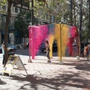
Studio H Plus proposes a new building for REALM Charter School that improves the interface between the school's students and the public at large. The building includes a large gallery space at street level that allows for exhibition of student work and engages pedestrians along the sidewalk. It also includes a creative kitchen intended to complement the existing Studio H curriculum and which is accessible directly from the street for use as an after-hours cooking school. The programs are organized around a central, double-height commons and dining space, which becomes the heart of the school and opens directly to outdoor courtyard space.
Step 2: Facade Design


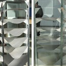
The proposed facade system consists of a custom-fabricated steel screen that modulates light according to careful calibration with solar exposure. The screen is projected off of the building mass, at times taking on secondary functions such as a horizontal canopy or an enclosure for an exterior stair. The system's components are L-shaped panels; when paired, they form a module with a central aperture that can increase or decrease in size parametrically based on requirements for daylighting, shading, and privacy.
The design team performed extensive analysis of the site and solar exposures in order to determine the gradating pattern of the apertures across the facade. The changing pattern responds to different programs on the inside of the building, and it also takes into account the changing path of the sun throughout the calendar year.
Step 3: Fabrication Process


Three prototypes were produced in the development of the facade system. Each of these prototypes was fabricated on the Omax waterjet at the Pier 9 Workshop in San Francisco. The process for each prototype included the following steps:
- Modeling of the parts in 3D software.
- Flattening / unrolling 3D geometry into a 2D line drawing.
- Export drawing as a DXF file.
- Complete toolpathing in the Omax Layout pathing software. Important considerations for these prototypes included making sure that the water jet (which has a thickness to it) was directed along the correct side of each cut line.
- Fabricate the parts using the Omax Make software.
The initial prototypes took direct inspiration from the paneling system developed in the initial farm stand project, which proposed parts with a large number of complex breaks. This proved very difficult to execute with 18 gauge steel, so the subsequent prototypes looked at simplifying this concept into a system of parts with simpler breaks that could perform in a similar way to produce a variable aperture in the center of the module. Other refinements included rounding the corners of each part so as to avoid sharp edges.
Step 4: Assembly Process


The prototypes were all assembled at CCA's shop. The bends in the panels were made both manually and using a press break. Standard steel unistrut framing was used for backup structure.
The assembly drawings above documents the assembly process both for the prototype and for a speculative installation on a building facade.
The exterior structure supporting the screen system is envisioned as a modular, prefabricated system of "super-panels" that would be fabricated off-site and delivered to the site for installation on the building.
Step 5: Final Prototype


The final prototype measures 45"w x 54"h and was presented at the studio's final review on May 3, 2014 at CCA.


