

Introduction: Arduino 2 Axis Time Lapse Dolly


It's about time I showed the internet my time lapse dolly. This is at least iteration 4 or 5, combining a linear motion rig with a panning rig, so unfortunately I don't have a step by step building process. But if your like me a photo is worth a thousand words. I assume seeing the final product will give folks lots of good ideas. I'll try and fill in the details of the build. Questions are always welcome.
I use a Nikon D5100, but the control mechanism should work for a wide variety of cameras (D7000 D5100 D5000 D3200 D3100 D90)
Summary of the key features:
-LCD readout of the number of photo's taken, total time since the start of the photo sequence, speed of the panning and linear motions, and interval between shots.
-Control of both speed and direction of panning and rotating axis.
-Stop/restart switch
-Direct connectivity to the Camera
-Highly adjustable camera mount for more complex motion paths
-Counter weight pulley system for higher angle (steeper) linear motions (I've done about 30 degree uphill pulls)
-Ramped acceleration profiles
Linear Motion:
The Dolly: This design has been used many times before but I feel like I added a couple clever features. First I built a pretty classic skate wheel dolly and set of round rails. You want to build the platform and skate wheel part first and then the rails to make sure the rails are spaced just right. I would say the skate wheels were the most expensive part of the whole build, but I didn't want to recycle old wheels and have a wobbly mechanism. The rail design folds up nice for transportation. I also threw in a couple pulleys so you can add a counter weight for steep climbs or descents.
The electro-mechanical design: I took apart a continuous rotation servo and soldered in a different motor that had a 100:1 gear box. This gave it a much higher torque and lower speed. I like the servo board's adjustment knob. Its helps tune the stop point for the pulse width signal that's sent from the arduino, but also makes for a super simple way to reel in or out your string. I drilled a hole slightly larger than the diameter of the shaft of the motor into the end of a machine screw and glued it together with metal epoxy . This is the axis of the spool of the reel for the string. The string pulls the whole skate wheel platform down the rails. I took a tiny piece of brass angle and drilled holes to mount the motor and bolted that into my platform. It needs to be on a slight angle to keep the string tight. I've programmed the servo to just go from kinda random -9 to 9, as I've played with it I've figured out how far it actually pulls. You can adjust it in the software if you want really long pulls.
Rotational Motion:
For this portion I took apart an old telescope tripod. This could become the most expensive part if you don't have one sitting around, about $75 on amazon. In fact having one just sitting around basically motivated the whole build. Anyway these tripod heads have quite a few different adjustable axis. At first I didn't think much of them, but as my motion paths have gotten more elaborate they have all become crucially important. There is a rotating axis right at the base, a tilting axis above that, another rotating axis above the tilt which is the motor driven axis, another rotating axis above that, and finally a tilting axis at the top that I took off. They usually have fine adjustment knobs, perfect little shafts to add a gear to. I had to build a mount for my camera. Luckily I had a super thick chunk of angle iron, a tap and die kit, and an angle grinder with plenty of disks. I attached my home made camera mount where I took off the top tilting axis. Paint it before you attach it or it may rust over like mine has. I decided not to go too cheap and attached a rather large stepper motor and I custom ordered a set of timing belt pulleys and a miniature timing belt. I got them from www.sdp-si.com. It was rather expensive and sparkfun just came out with a whole line of robotic parts I would certainly have used at the time. I used my calipers to measure out the whole pattern on the front of the stepper and drilled it into a spare piece of aluminum angle. I mounted the angle to some pre-existing holes and bolts on the tripod head and it works like a charm.
I used an easydriver stepper motor driver and the Stepper Motor - 125 oz.in (200 steps/rev) from sparkfun. To change the direction of rotation you can simply flip the four leads over (green black blue red) to (red blue black green). You can also handle this on the software side, I didn't. The readout on the LCD is the number of steps the motor is going to spin. You can scale this to you gear ratio, start slow!
A couple notes about the rotating axis:
I have tried to use a stepper motor with a camera fastened directly to the end of the shaft and it was a frustrating and painful endeavor. Even with a 400 steps per revolution motor and micro-stepping motor driver I really couldn't get smooth rotations. It was crucial to me to gear the mechanism down. Microstepping drivers running off batteries didn't hold at the micro steps very well, often skipping and creating choppy motion. Gearing it down meant I can use 10 or 15 steps and still have extremely slow movement. When your camera's pointed at something really far away a 1 degree rotation is a huge jump. Even at 24 frames per second, or 24 degree's per second, your video's are going to make you feel sick.
The use of a telescope tripod head was also a huge advantage. This mechanism is clever in that it uses a worm gear. These gears mechanisms don't transmit force backwards, so it holds itself in place very well even if the camera isn't totally balanced. When you get into weird motion paths this helps.
Communication to the Camera:
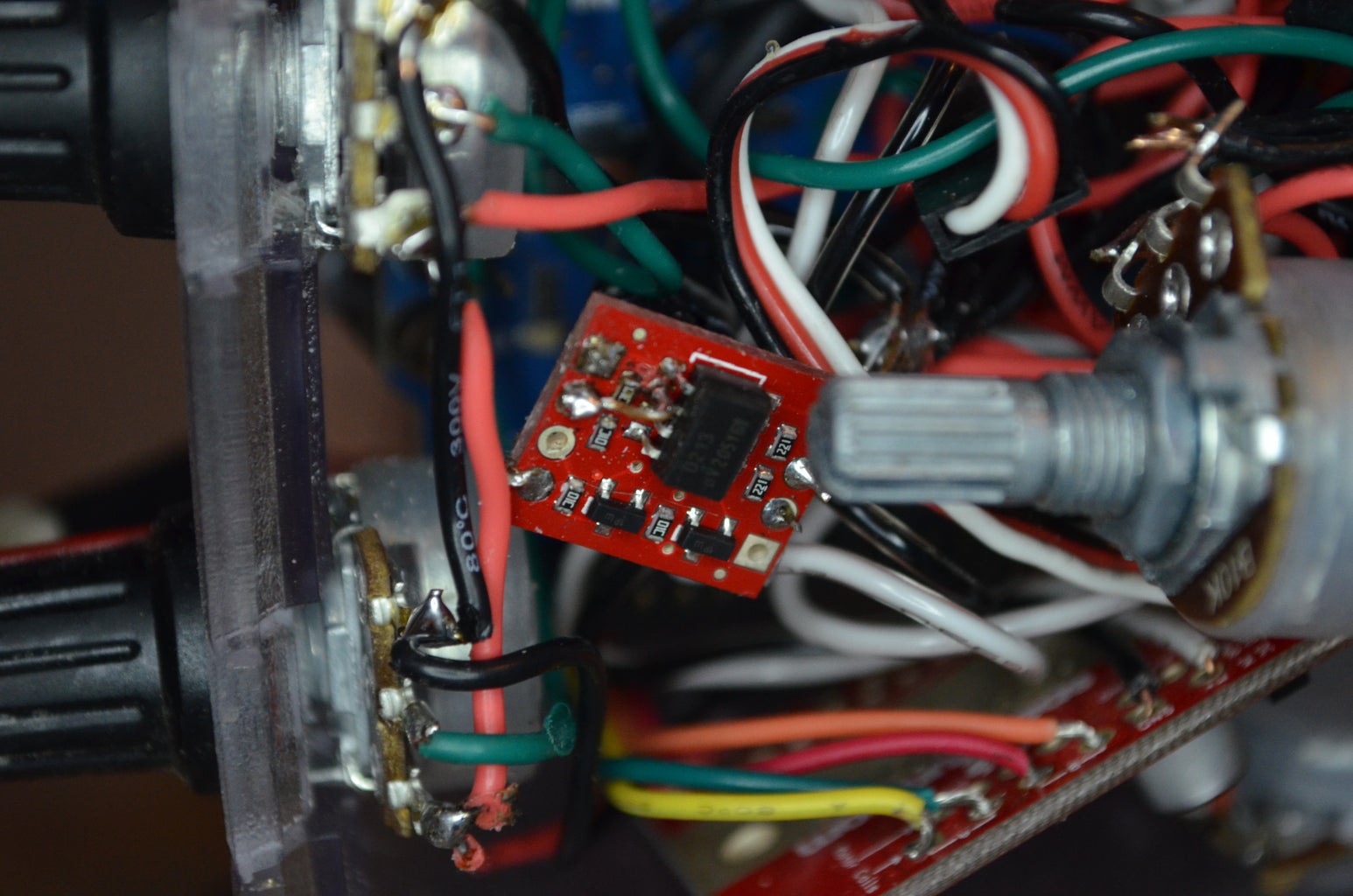
I have used IR LED's in the past and haven't been totally successful. It worked for sure, but if its really bright out they seem to loose their strength. Or if you camera rotates out of the view of the LED... So on this rig I took apart a wired shutter release button I got from amazon. It was super simple inside. It had 3 little plates that when you pressed down the button pushed together the plates made a connection to ground, and activated the shutter. So to imitate this with my arduino I used an opto-isolator. This was actually a little tricky, it didn't work right of the bat and I had to jump a couple of the leads. I don't know exactly what I did, but it works, unless its really cold out. I believe I just skipped over a resistor. If its really cold I just use the internal intervalometer. I would love for some help on this if anyone knows a temperature independent solution.
Power:
I've gotten it powered a couple different ways. The best of which is a hacked car cigarette lighter. I also bought a little 12V lead acid battery from a battery store that I charge off a universal charger. A couple 9 volts wired in parallel works good too, just expensive. I put a power switch on the positive lead of the battery so I can turn it off an on. When the batteries start to die the stepper motor is the first to loose adequate strength, then the pulling motor, and finally the LCD and arduino. I have had some interesting non-linear motion behaviors due to this that I don't love but don't hate. After using the rig 50 or so times I've developed a intuition on whats going to happen and usually get pretty decent results. I'm not about to go shoot for Nat Geo unless I upgrade my batteries though.
Software:
I've attached a copy of the software down below. You'll want to download the arduino software and all the appropriate libraries (AccelStepper, liquidCrystal). Definitely feel free to shoot me any questions you may have concerning the software, its on iteration like 103. It basically reads the input from 3 potentiometers and a spdt switch. The pot's determine the interval and the speeds of the two axis. The switch is just a stop switch. It holds the program in a loop that updates the display but doesn't send any signals to the motors. Once you've flipped the switch it starts a timer, sends signals to the camera to take a shot, sends signals to the motors after taking the shot, counts the photos, all while updating the display. I was never formally trained in code writing so its probably pretty rough. But hey, it gets the job done!
Feel free to shoot me any questions you have about the build. I've got a few video's on Vimeo if you want to see some fruits of the labor (https://vimeo.com/user8764758)
Thanks for checking my project out!
Attachments


Participated in the
Hardware Hacking


