

Introduction: Arduino Analog Thermometer


This analog thermometer is controlled by an Arduino Uno board. It uses a temperature sensor to feel the room temperature (or even your body temperture if you touch the sensor with your fingers) and it converts the analog input of the sensor to Pulse With Modulation (PWM) output that moves a servo motor between 0 and 180º. This servo motor has a pointer at the end of its shaft that tells you the current temperature.
The Arduino board, the breadboard and electronic parts are fitted inside a plastic container and a 9V battery supplies power to the circuit so the thermometer becomes an autonomous gadget.
Step 1: Parts and Tools

Parts:
- Arduino Uno board
- 9V battery and snap
- Temperature sensor TMP36
- Servo motor SM-S2309S
- 1 blue LED and 1 red LED
- 2 resistors 220 ohm
- Some jumper wires
- Plastic container
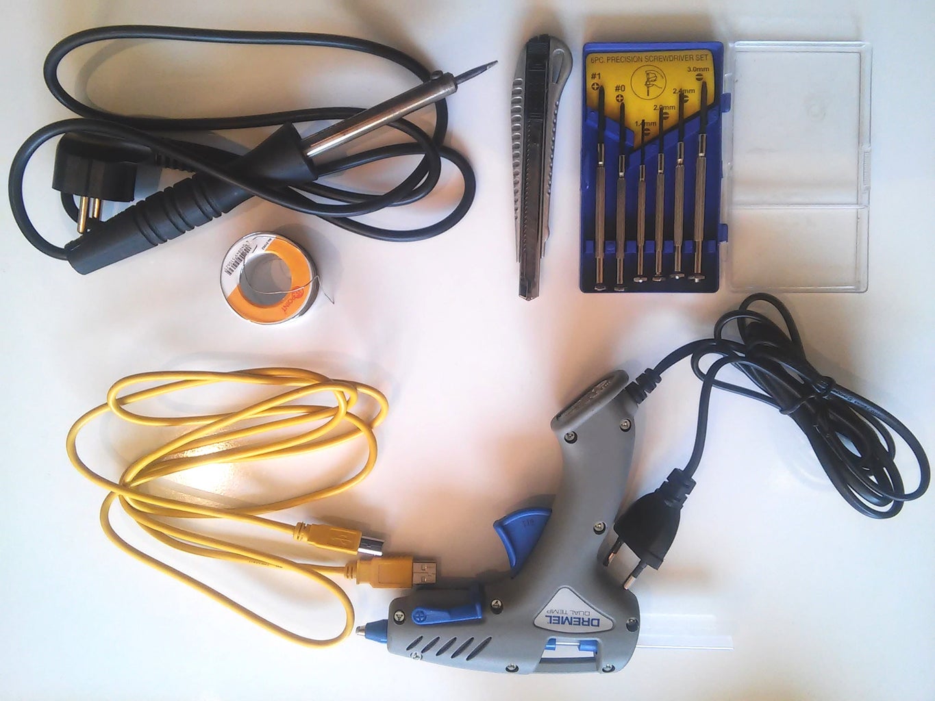
Tools:
- USB cable
- Silicone glue gun
- Screwdrivers
- Soldering set
- Cutter
.......................
Step 2: Wiring the Circuit


In this step we will place the electronic parts on the breadboard and connect them with wires. Refer to the enclosed circuit diagram to see all the elements and conections.
Place the temperature sensor near the top-left corner of the breadboard and plug one leg to the positive vertical strip, one leg to the negative and the center leg to analog input pin A0. Be careful, the order of the pins is important, look at the picture.
Wire the left positive strip to 3.3V pin on the Arduino and negative strip to ground (GND).
At the top-right side of the breadboard attach the servo motor connector. Then, connect positive and negative pins to the positive and negative strips on the right of the breadboard, and wire center pin to Arduino digital pin 9. Power this side from Arduino 5V pin and wire it to the ground (GND). It's important to power the servo motor and the temperature sensor from different sources (5V and 3.3V). The servo draws a lot of current when it starts to move and causes a dip in the voltatge in the circuit that would affect temp. sensor readings if they were placed in the same circuit.
Place two 220-ohm resistors at the bottom-left part of the breadboard, one leg attached to the negative strip.
Solder wires to the legs of the LEDs and connect the blue LED anode to digital pin 2 and the red LED anode to digital pin 3. Connect the cathodes to the ground.
At the end, connect your 9V battery positive pole to pin VIN in the Arduino and negative wire to ground pin. You can power your Arduino from an external source (7V-12V) using the VIN pin.
Step 3: Building a Container


Now it's time to search for a box to enclose our Arduino circuit. It can be a plastic or cardboard box and its size should be at least 12x12x8 cm. In my case, I bought a cheese container made of plastic (just for 1€!). This triangular container gives a particular shape to the analog thermometer, but you can also use a common square box.
Once you have your container you will need to make some holes:
- Drill some holes at the back of the box to let ambient air in.
- Cut a square hole 10x10 mm to allow you plug the USB cable to the Arduino board when placed inside the box.
- Cut a rectangular hole 12x24 mm at the center of the container cover to place the servo.
- Drill also two holes Ø5mm, one at the left and the other at the right of the cover. You will introduce the LEDs in these holes.
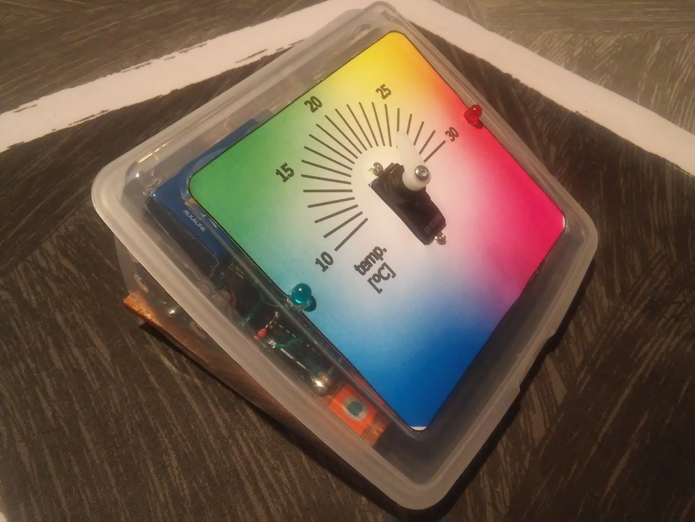
Step 4: Print a Temperature Sticker

You can design your own sticker and glue it to the cover of your container. In my thermometer, temperature goes from 10ºC to 30ºC, but if you modify these min/max values in the Arduino program, you can set your thermometer to work within another range of temperatures.
I attached a PDF file with the circular colored temperature scale that I printed and glued to my thermometer.

Step 5: Put Everything Together


Now it's time to:
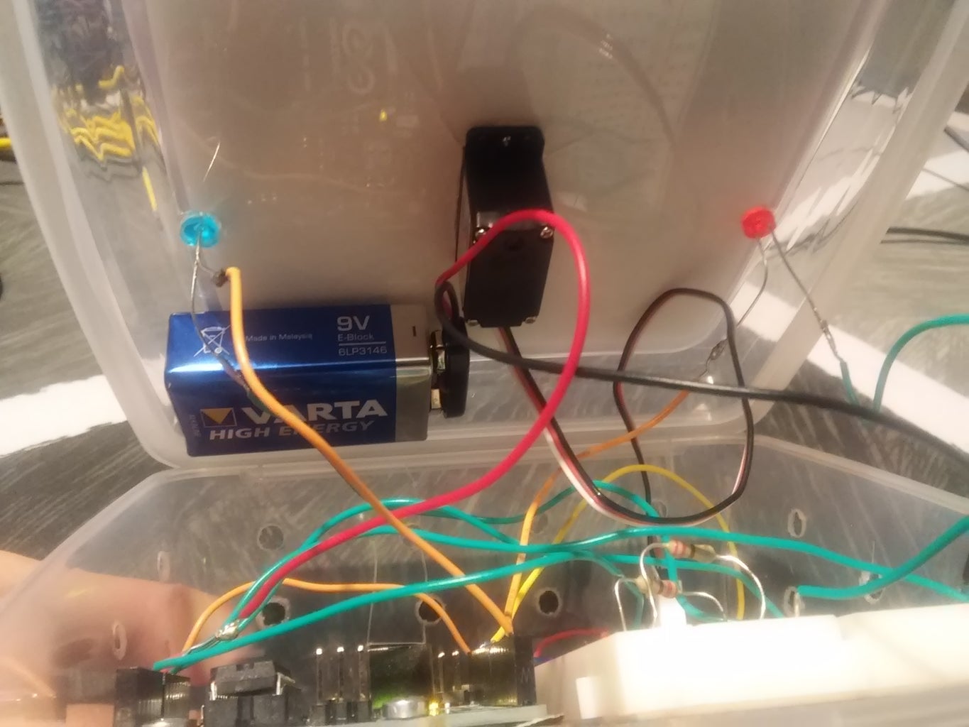
- Glue the 9V battery under the container cover. I used a silicone glue gun.
- Place the servo motor in the 12x24mm hole with 2 little screws (or silicon glue).
- Introduce the Arduino board and the breadboard into the box. Try to attach it to the box base so it can't move (gluing it or with a similar procedure).
- Place the blue and red LEDs through the drilled holes in the cover
- Connect the servo connector (with 3 male headers) to the breadbord (refer to Step 2).
- Connect the battery to the Arduino board as described in Step 2.
Step 6: Write the Arduino Code and Download It


This is the last step: give the code to your Arduino board as it can work as an analog thermometer.
I attached a file with the Arduino sketch I used.
The sketch uses the library "Servo.h" to control the position angle of the servo motor (0-180º)
Then there are some variables and constants. The constants minTemp and maxTemp are the minimum and maximum temperature values that the thermometer will display. The minTemp value corresponds to servo angle=0 and maxTemp to angle=180 (maximum angle). Of course, you can vary these values to suit the temperatures in your room or your country (it's not the same to be in Barcelona or Moscow, for example). You can also read the temperature of your body by touching the sensor with your fingers.
The servo will rotate to a position between 0 and 180º, proportional to the temperature read by the sensor and to the given min/max temperatures.
Blue LED will light up when temperature is below minTemp (10º)
Red LED will light up when temperature is above maxTemp (30º)
Finally you can download the program to your Arduino with the USB cable and see how it works. If you keep the cable connected you will be able to open the serial monitor of Arduino interface and see the sensor, voltage, temperature and servo angle values.
Then, you can unplug the cable and place your thermometer wherever you prefer (it uses the 9V battery to supply itself).


Participated in the
Epilog Contest 8

Participated in the
Arduino Contest 2016


