

Introduction: How to Make Arduino Based Collision Detection Warning System


Step 1: Items and Material Required

Please gather the following items
- Computer :- This is required to write program and flash program to controller. Also you need to install arduino IDE which is available free at arduino website download section.
- Controller :- I used arduino micro-controller. This you can get at online seller like amazon etc.
- Sensor :- I used HR SC-04 ultrasonic sensor.
- Piezo Buzzer :- I used piezo buzzer to make audio warning.
- LED :- There is two type of LED i used to which is red LED and blue LED.
- Wires :- There were jumper wires required to make hardware connections. You need to take all type of jumper wires like both end male, both end female and one end male another end female type.
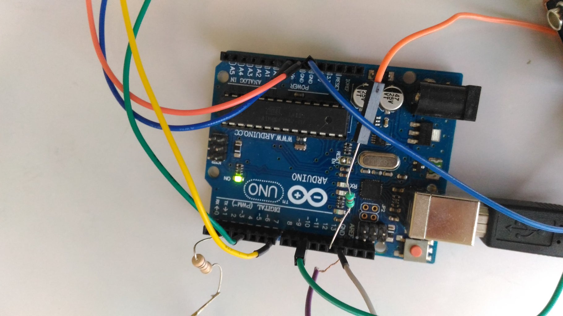
Step 2: Connect All Hardwares


The hardware you gather in first step, now connect all them to controller through wires.
Sensor to controller pin information :-
Sensor has four pins VCC, Trig, Echo and GND. Connect...
VCC pin to 5V on controller
GND pin to GND on controller
Trig pin to pin-7 on controller
Echo pin to pin-4 on controller
Piezo Buzzer to controller pin information :-
Piezo buzzer has two pin.
Connect one pin to pin-10 on controller
Connect another pin to GND on controller
Red LED to controller pin information :-
Red LED has two pin.
Connect one pin to pin-2 on controller
Connect another pin to GND on controller
Red LED to controller pin information :-
Red LED has two pin.
Connect one pin to pin-13 on controller
Connect another pin to GND on controller
Controller to Computer connection information :-
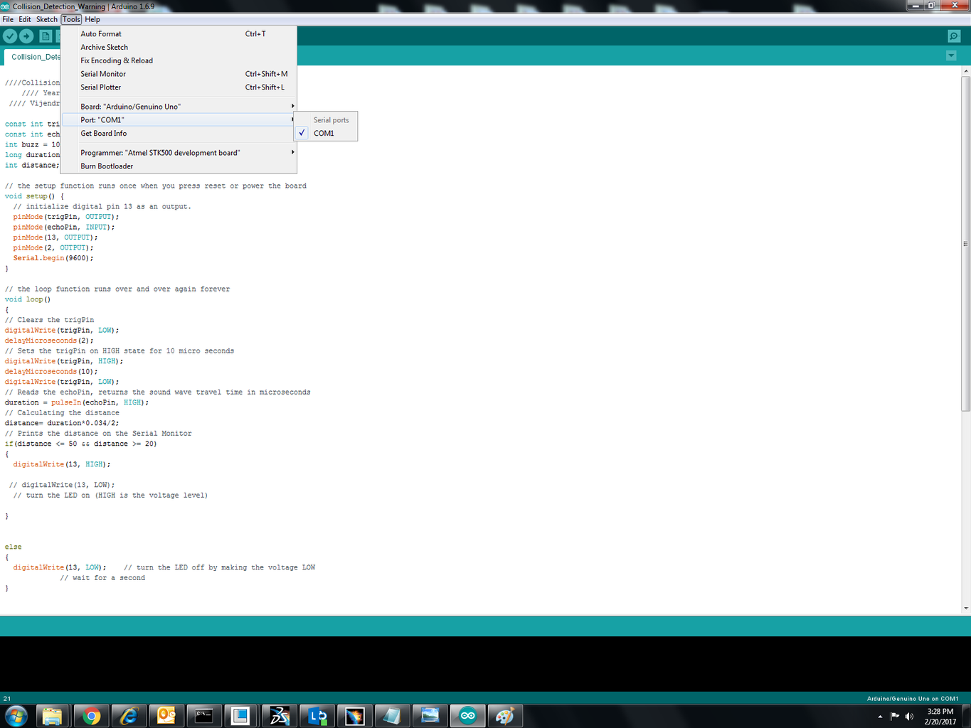
You have USB data cable that you got while buying arduino. By this data cable you connect computer to arduino board.Now launch the arduino IDE. After connecting to computer you must have to select board and port from menu.
please see the attached screen shot for the help.
Step 3: Write Arduino Program

In the previous step we defined pin information for the hardware. No that info we'll use to write program instructions.
Launch Arduino IDE and try to write program by yourself. Otherwise you can directly use my program or download the .ino format file attached.
While copying this code you have to be careful because some character used in program cannot be paste while writing this on instructable. Better to download .ino format file.
////Collision Warning System////
//// Year 2017 ////
//// Vijendra Kumar////
const int trigPin = 7;
const int echoPin = 4;
int buzz = 10;
long duration;
int distance;
// the setup function runs once when you press reset or power the board
void setup() {
// initialize digital pin 13 as an output.
pinMode(trigPin, OUTPUT);
pinMode(echoPin, INPUT);
pinMode(13, OUTPUT);
pinMode(2, OUTPUT);
Serial.begin(9600);
}
// the loop function runs over and over again forever
void loop()
{
// Clears the trigPin
digitalWrite(trigPin, LOW);
delayMicroseconds(2);
// Sets the trigPin on HIGH state for 10 micro seconds
digitalWrite(trigPin, HIGH);
delayMicroseconds(10);
digitalWrite(trigPin, LOW);
// Reads the echoPin, returns the sound wave travel time in microseconds
duration = pulseIn(echoPin, HIGH);
// Calculating the distance
distance= duration*0.034/2;
// Prints the distance on the Serial Monitor
if(distance <= 50 && distance >= 20)
{
digitalWrite(13, HIGH);
// digitalWrite(13, LOW);
// turn the LED on (HIGH is the voltage level)
}
else
{
digitalWrite(13, LOW); // turn the LED off by making the voltage LOW
// wait for a second
}
if(distance <= 20)
{
digitalWrite(2, HIGH);
tone(buzz, 2000);
delay(100);
noTone(buzz);
delay(100);
tone(buzz, 2000);
delay(100);
noTone(buzz);
delay(100);
tone(buzz, 2000);
delay(100);
noTone(buzz);
tone(buzz, 2000);
delay(100);
noTone(buzz);
delay(100);
}
else
{
digitalWrite(2, LOW); // turn the LED off by making the voltage LOW
// wait for a second
}
}

Step 4: Flash Arduino Board

After making all connection we are ready to upload the program to arduino board. Please see the attached image for reference.
Step 5: How This System Works
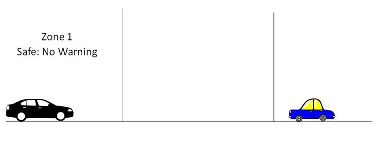


Let me explain you that how this system works.
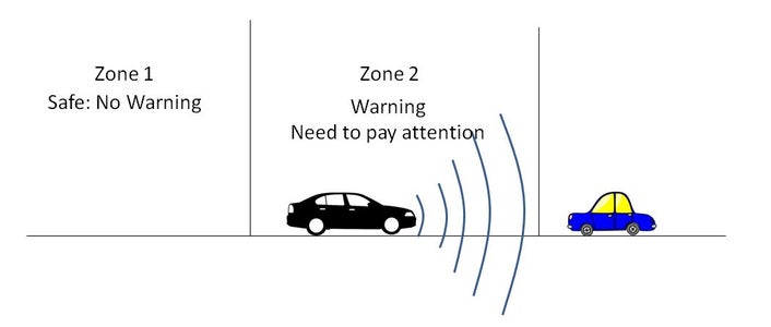
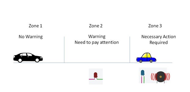
I defined three different zones.
Zone 1 :- No warning
Zone 2 :- Only visual warning (In this zone driver has to pay attention)
Zone 3 :- Both visual and audio warning ( Driver has to take necessary action to avoid collision)
Step 6: Test You Setup
Now whole system is ready to test. Please see the Both video to see the how to check the system is working.

Participated in the
Sensors Contest 2017

Participated in the
Microcontroller Contest 2017


