

Introduction: Arduino Based (JETI) PPM to USB Joystick Converter for FSX


I decided to switch my JETI DC-16 transmitter from Mode 2 to Mode 1, which basically switches Throttle and Elevator from left to right and vice versa. Since I didn't want to crash one of my models due to some left/right confusion in my brain, I was wondering whether it is possible to practice a little bit in FSX.
I read and tested the JETI transmitters actually support a Joystick mode out of the box, however I wanted full flexibility for the axes and switches assignments and use the TX as with a real model. By using the receiver's output, it is also possible to leverage the signal processing in the DC-16 and use mixers, flight phases, dual rates, whatever you can program there.
Recently I found a nice tutorial on how to make a USB HID input device, namely a Joystick, out of a cheap Arduino like a Pro Micro:
https://www.instructables.com/id/Create-a-Joystick...
This would enable everything needed to control a plane / helicopter / whatever in FSX! Plenty of axes and buttons available.
Since I just had a spare JETI RSAT2, I decided to wire it up with the Arduino and try to implement a small PPM parser along with the Joystick library.
I am assuming anybody following these steps is familiar with connecting and programming an Arduino. I will not take any warranties for malfunctions or damages!
Supplies
You will need...
- any Arduino supported by the Joystick library, I used a Sparkfun Pro Micro 5V / 16 MHz
- a recent version of the Arduino IDE
- any RC receiver outputting a PPM signal, like the JETI RSAT2
- a few jumper wires (min. 3)
- the Joystick library installed in the Arduino IDE
- the arduino-timer library: https://github.com/contrem/arduino-timer
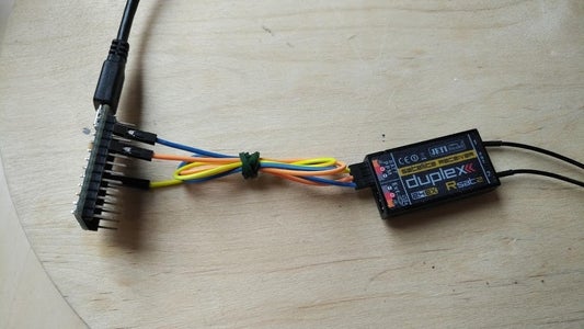
Step 1: Wire Up the RX and the Arduino


The wiring is pretty much straightforward. I decided to only power the Arduino from USB, since it shall emulate a Joystick device. This will supply the Arduino with 5V, which can be used also for powering the RC receiver.
I used the Pin VCC, which provides regulated output, and the nearest Gnd pin - just connect it to the PPM's connector + and - pins. When the Arduino gets powered, the receiver is now powering up, too.
For the PPM signal, I decided to use interrupts to parse them. Interrupts are available e.g. at Pin 3, so just connect it there - there is no "native RC pin" on the arduino, but possibly more and different ways to read in the receiver signal.
I had to disable the RX voltage alarm, since the VCC voltage with USB supply will be around 4.5V only - but quite stable, so no problem at all.
Step 2: Getting Some PPM Signals


When the receiver AND the TX is powered, I was getting PPM signals like shown in the image. 16 channels, repeated forever. If Failsafe on the RSAT is disabled and the transmitter powered off, PPM output will be disabled.
More information on PPM is available here:
Since I am not flying real stuff in this case, I didn't care for the theoretical timings and just figured out on the oscilloscope what my receiver was acutally outputting when moving the sticks from fully left to fully right (standard settings in the TX). It seemed -100% corresponds to pulses with a length of 600µs, and +100% to 1600µs. I also didn't care for the length of the pause pulses (400µs) in my Arduino code, but I assumed a frame spacing of min. 3000µs.
Step 3: Configuring the Transmitter


Since only the actual position of the control surfaces needs to be known, one channel / "servo" per RC function is sufficient. Consequently, a rather simple transmitter setup can be made - similar to a normal RC model. The main functions aileron, elevator, rudder and throttle each require only one servo respectively transmitter channel. I also added flaps, brakes and gear, leaving 9 channels free so far. Please note that Flaps were put on a flight phase, and are not controlled directly via a stick, slider or button.
Step 4: Running the Joystick


The Joystick library is quite easy to use, and provides some examples and tests. It should be helpful to first check if the Arduino is detected as proper Joystick, the instructions linked in the entry section and the library itself provide some good guidance.
In the Devices and Printers control panel, the Arduino was showing up as "Sparkfun Pro Micro", and the joystick test window was showing 7 axes and plenty of supported buttons. Even a hat switch can be used when programmed in the Arduino.
Step 5: Coding the Arduino


What's still missing is the actual parsing of the PPM signal and assignment to Joystick axes and buttons. I decided for the following mapping:
Channel / Function / Joystick assignment:
- Throttle -> Throttle axis
- Aileron -> X axis
- Elevator -> Y axis
- Rudder -> X rotation axis
- Flaps -> Y rotation axis
- Brake -> Z axis
- Gear -> Button 0
When the gear is down, the first button of the Joystick shall be pressed and will be released when raising the gear. However, this will require FSUIPC for FSX, out of the box, FSX will accept only a button for toggling the gear, which is not exactly what's happening with my models.
I provided my current version of the code with a lot of comments, which is working quite well for me - feel free to change your assignment or add new functions. The last 9 RC channels are currently not used.
For the setup, the Joystick class needs to be initialized, basically by defining the numeric axis ranges:
/* Set axes range (defined in the header, 0 - 1000) */
Joystick.setXAxisRange(CHANNEL_MIN, CHANNEL_MAX);
Joystick.setYAxisRange(CHANNEL_MIN, CHANNEL_MAX);
...
By using values from 0 to 1000, it is possible to directly map the pulse length (600 - 1600µs) to the joystick values without rescaling.
The DIN 3 is initialized as digital input, pullups enabled, and an interrupt attached:
pinMode(PPM_PIN, INPUT_PULLUP);
attachInterrupt(digitalPinToInterrupt(PPM_PIN), PPM_Pin_Changed, CHANGE );
For debugging purposes, I added some printouts via the Serial interface in regular intervals, using the arduino-timer library:
if(SERIAL_PRINT_INTERVAL > 0) {
  scheduler.every(SERIAL_PRINT_INTERVAL, [](void*) -> bool { SerialPrintChannels(); return true; });
}
The pin's interrupt will be called whenever the pin's logical value has changed, so for each edge in the PPM signal. Evaluate the pulse length just by simple timing using micros():
uint32_t curTime = micros();
uint32_t pulseLength = curTime - edgeTime;
uint8_t curState = digitalRead(PPM_PIN);
By evaluating the current pin's state and combining it with the pulse length and past pulses, the new pulses can be classified. Following conditional will detect the interframe gap:
if(lastState == 0 && pulseLength > 3000 && pulseLength < 6000)
For subsequent pulses, the pulse length will be mapped to an axis state by clipping and biasing the pulse length to match the joystick axis range:
uint16_t rxLength = pulseLength;
rxLength = (rxLength > 1600) ? 1600 : rxLength;
rxLength = (rxLength < 600) ? 600 : rxLength;
rxChannels[curChannel] = rxLength - 600;
The rxChannels array eventually contains 16 values from 0 - 1000, indicating stick / slider and button positions.
After receiving 16 channels, the mapping to the Joystick is performed:
/* axes */
Joystick.setThrottle(channels[0]);
Joystick.setXAxis(channels[1]);
Joystick.setYAxis(1000 - channels[2]);
Joystick.setRxAxis(channels[3]);
Joystick.setRyAxis(channels[4]);
Joystick.setZAxis(1000 - channels[5]);

/* buttons */
Joystick.setButton(0, (channels[6] < 500 ? 1 : 0));

/* update data via USB */
Joystick.sendState();
I inverted some axes in the code, which is not absolutey necessary, since axis can also be inverted by flipping servo direction or the assignment in FSX. However, I decided to keep the servo directions and also the original FSX assignment.
The button is switched on or off by thresholding channel 7.
And don't forget to tick the scheduler...otherwise, no debug prints will be visible.
void loop() {
  scheduler.tick();
}
In the screenshot I attached you can see, channel 1 was moved from 1000 (full throttle) to 0 (idle).
FSX will detect the Arduino just as any other Joystick, so just assign the button and axes and have fun taking off!
What I really like about this approach is, you can just use your transmitter as with a real model, e.g. using flight phases etc.


Participated in the
Arduino Contest 2020


