

Introduction: Arduino Basic PC With VGA Output


In my previous Instructable I have shown how to build a retro 8-bit computer running BASIC, by means of two Arduino, and with an output signal in B&W for a TV screen.
Now I will show how to build the same computer, but with the output signal in color for a VGA monitor!
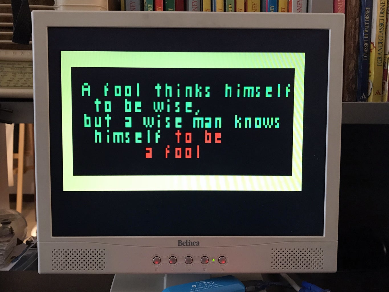
You can input the variables and the BASIC program with a PS2 keyboard, and it generates the output for a VGA monitor with a text resolution of 24 columns x 10 rows of 5x6 pixels characters, in four colors. You can see it in action in the upper video. The program can then be saved on the Arduino EEPROM, and you can still control the I/O pins directly via Basic dedicated commands.
This project can also be used to print simple text messages on the monitor, as shown in the third picture in this page.
One Arduino is the "master", and it runs Tiny Basic Plus, a C implementation of Tiny Basic, with a focus on support for Arduino. It also control a PS2 keyboard. The output is then sent via the serial port to the second Arduino which generates the VGA output thanks to the VGAx library.
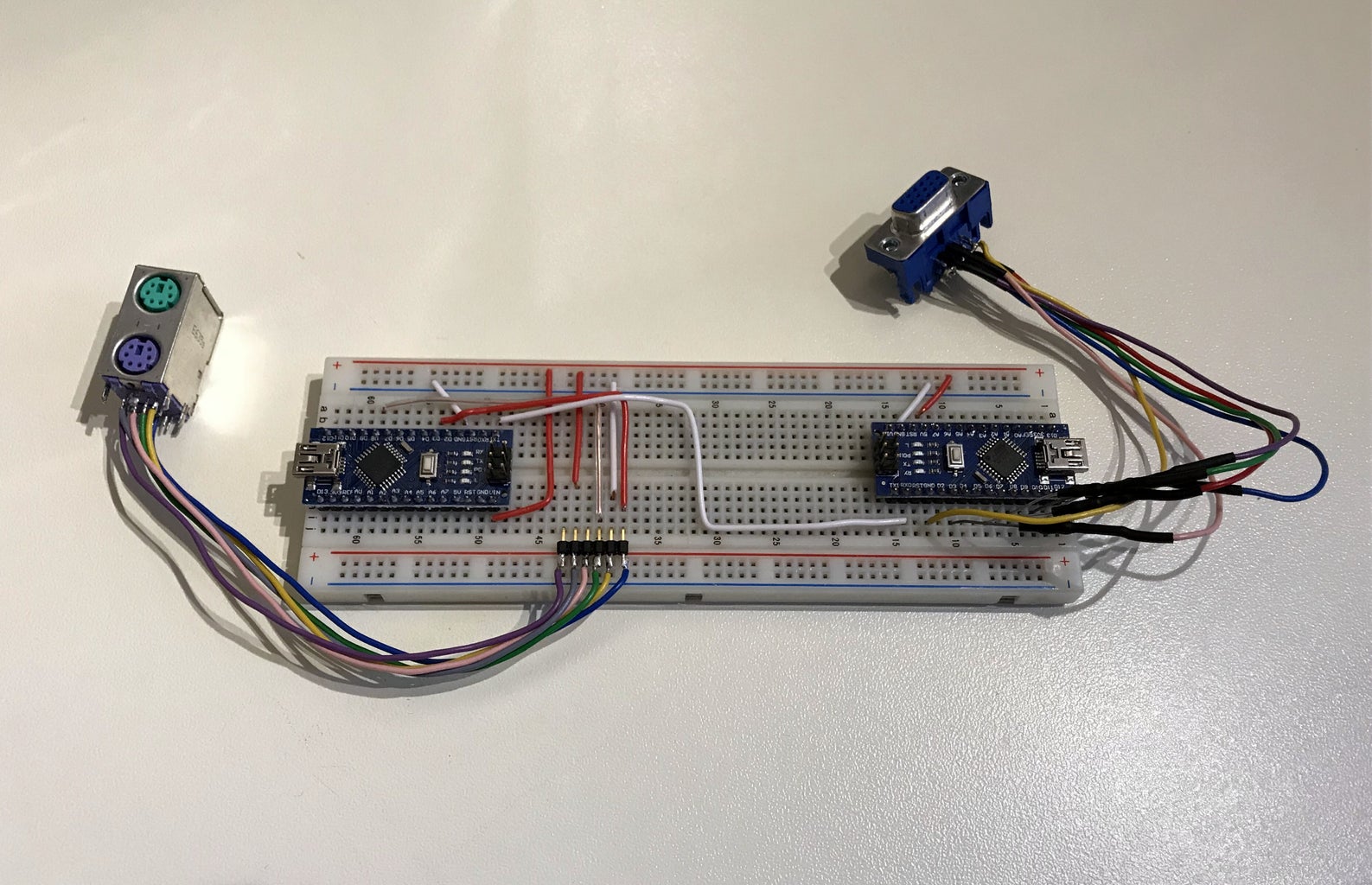
The idea to use one or more Arduino to create an old style PC running a dialect of Basic is not new but, as far as I know, none of them has a color output. In some projects available on the net, people used LCD displays, while in others, to allow the use of monitors, it has been used the TVout library, which is B&W. Furthermore in many of these projects special shields or hardware has to be build. Here you need just two Arduino, few resistors and the connector for the PS2 keyboard and the monitor, as shown in the above pictures.
Step 1: Build the Arduino Master With TinyBasic and PS2 Keyboard
TinyBasic Plus and the VGAx library work for Arduino IDE 1.6.4.
First download it from the Arduino official web page. If you have a newer versions on your PC, the best is to download it in .zip format and uncompress them on your PC. Click this link to download the Windows version.
You need then the PS2keyboard library. You can find it at the bottom of this page. Just uncompress it and copy the PS2keyboard folder in: arduino-1.6.4\libraries
Finally, in this page, download the file: TinyBasicPlus_PS2_VGAx.ino, uncompress and upload it on your Arduino.
This is a variation of the standard TinyBasic Plus where i have added the PS2 library and modified the code to accept the variables from it.
More details on TiniBasic Plus and tutorials can be found at this link.
If there are no problems, and compatibility issues, Tiny Basic is already running. You can test it trough a serial monitor in your PC. For this purpose I use PuTTY, but many other programs are available.
You have to set the correct COM port (it is the same you find in the Arduino IDE) and baud rate = 4800
Here you can already test some program in Basic just by typing them with your PC keyboard (NB later on I will show how to connect the PS2 keyboard directly to the Arduino).
Try for instance:
10 PRINT "Hello, World!"
20 GOTO 10
RUN
You can then stop the infinite loop just by typing ctrl+c.
Note that this combination will not work for the PS2 keyboard.
In the next step I will show how to connect the PS2 keyboard to Arduino.

Step 2: Connect the PS2 Keyboard to the Master Arduino

I got all the informations and library from this Instructable.
Essentially you need to connect the folowing four pins:
- keyboard Data to Arduino pin 8,
- keyboard IRQ (clock) to Arduino pin 3;
- you need to connenct GND and +5V as well.
I got an old PS2 female connector from a broken PC motherboard. You can simply unsold it with a heat gun.
In the picture shown in this step, you can find the function of the needed pins of the PS2 connector.
Step 3: Upload the VGAx Library and Code on the Second Arduino and Put Everything Together
First download VGAx-PC.ino code at the bottom of this page and copy it on your PC in a directory with the same name.
Download the VGAx library from this link on GitHub. The easiest way is to copy it in the Arduino software subfolder named "libraries", to be immediately recognized.
IMPORTANT: this library works for Arduno IDE 1.6.4 but it is not fully compatible with elder or newer versions.
Upload the VGAx-PC.ino in your second Arduino board (I tested it for the Nano version but the Uno should work as well).
A warning for low available memory is normal. If you do not have other errors everything is ok and you can immediately start to build your own 8-bit PC.
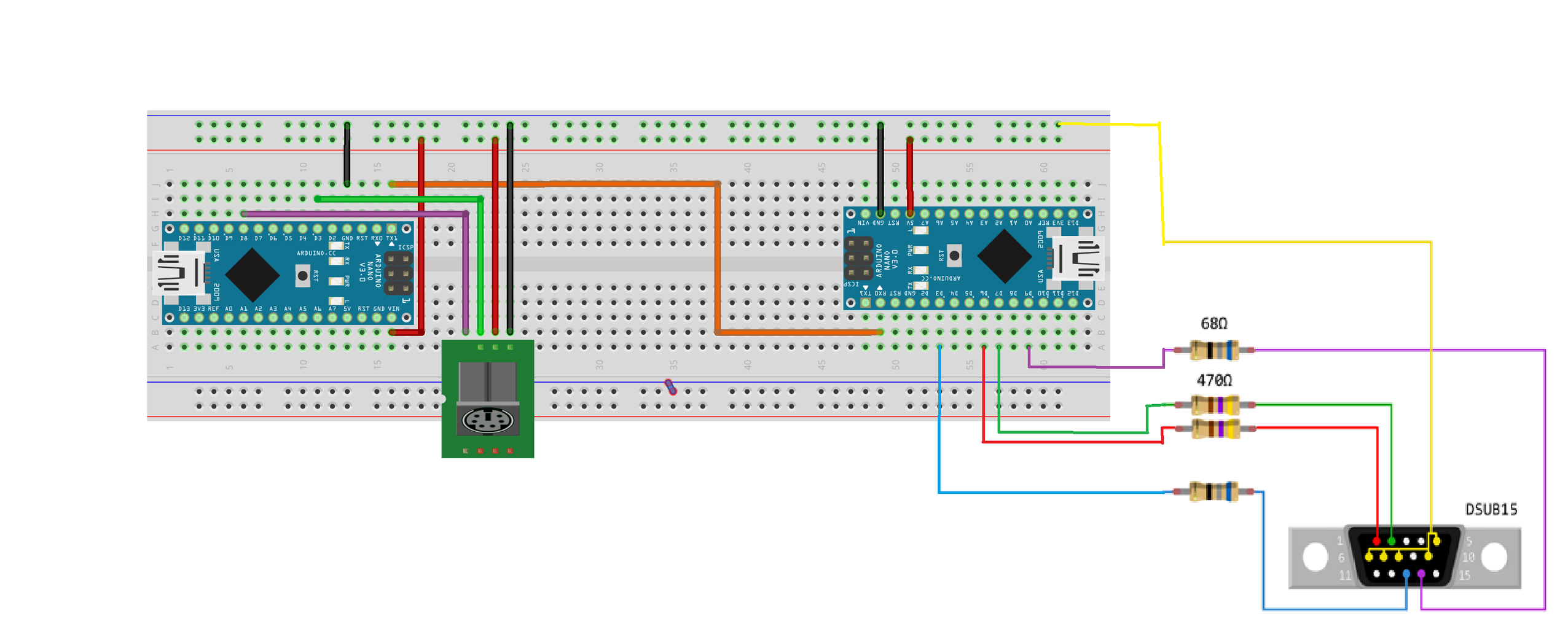
For this you need:
- two Arduino Uno Rev. 3 or two Arduino Nano 3.x (ATmega328)
- a DSUB15 Connector, i.e. a VGA female connector or a VGA cable to be cut.
- resistors: 2 x 68 Ohm and 2 x 470 Ohm
- a PS2 female connector
- wires
- facultative: a breadboard or a strip board
The schematic is reported at the top of this step. An example of a finished “console” is shown in the introductive step.
The same schematic, with an higher resolution, is reported in a compressed file at the bottom of this step.
Step 4: Optional: Using a PCB

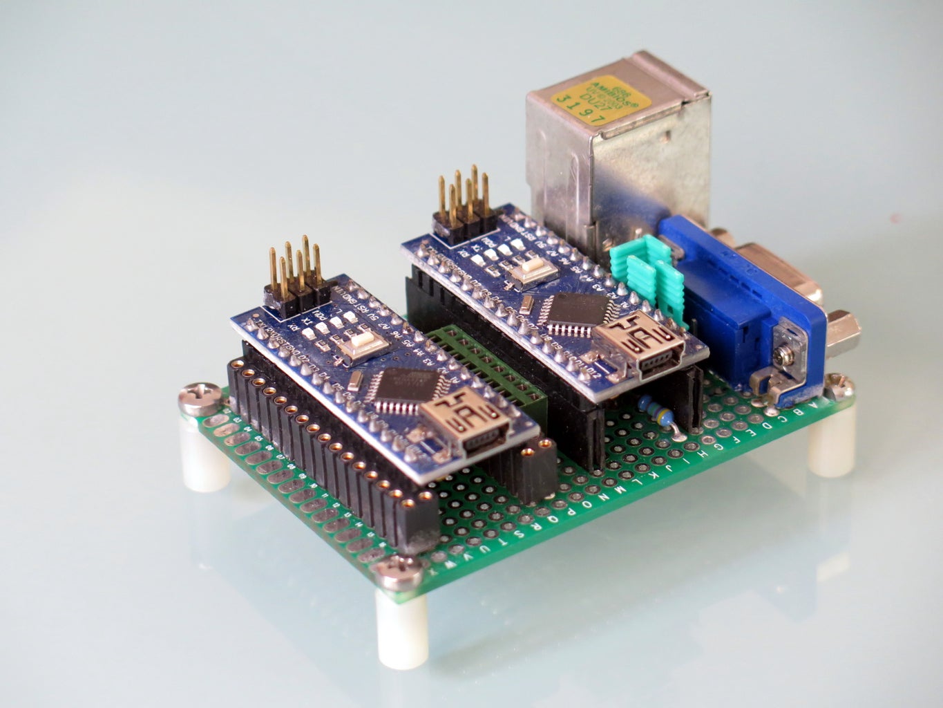


You can also build this Basic VGA PC using a small PCB. You can take inspiration from the pictures in this step or you can even print your own board.
I used two female header strips with 15 holes for the video output Arduino, while for the master I used two strips with doble holes. In this way I can use the external ones to insert the contacts of other projects componets, that can be driven directly with Basic code. I also added in the center to leftover strips, one conncted to 5 V and the other for GND.
Step 5: Final Comments and Acknowledgments
My main aknowledgement goes to Sandro Maffiodo aka Smaffer, the creator of the awesome VGAx library.
Many thanks also to the authors of TinyBasic Plus:
- Tiny Basic 68k - Gordon Brandly
- Arduino Basic / Tiny Basic C - Michael Field
- Tiny Basic Plus - Scott Lawrence
Thanks also to "djsadeepa", the author of the Instructable for the connection of the PS2 keyboard.
To all the people interested in this project: if you have troubles, do not hesitate to ask suggestions in the comments.
If you succeed, please write a comment too or share a picture of the device you build.


