

Introduction: Arduino Binary 7 Segment Display Clock & Calendar


Unlike most other binary clocks this clock displays the binary time and date on 3 rows of 8 seven segment displays as one and zeroes rather than just rows of LEDs.
Full details on this my web site here.
An Arduino 328 Microprocessor is used to decode and display Time & date from the DCF77 "Atomic" Clock in Mainflingen near Frankfurt Germany
The DCF77 signal is decoded using the fantastic new DCF77 library written by Udo Klein meaning the clock stays in sync and keeps perfect time even with a massive amount of noise on the received DCF77 signal. Udo Klein's DCF77 library continually "Auto Tunes" the quartz crystal so in the rare event the signal can't be decoded the clock remains accurate within 1 sec over many days. I didn't want any switches on the clock so time display mode switching are carried out by 433MHZ remote control.
Specs
3 rows of 8 seven segment displays show time and date in binary
Time can be displayed in Binary coded decimal or Binary format
Main clock display can be remotely switched between full binary time display, binary coded decimal time and full binary display of date
Time and date is synchronized to the DCF77 time code transmitter is Germany
Main display brightness is auto adjusted to room level
PIR sensor automatically shuts down the main 7 segment display and LCD display when no one is in the room
USB connection for serial programming and reading via a CP2102 USB to UART / TTL Adapter
A Secondary 4x20 I2C LCD display is used to display time & date, display brightness, sync information,
signal quality, auto tune'd frequency and auto tuned quartz accuracy. The display also shows decimal time and date which is handy when you are learning to decode the binary displays in your head.
Step 1: Background


I have built a few binary clocks in the past. My first Binary clock was built in 1985 and was built into an old pendulum clock see image 2. The pendulum operated a contact every 0.5 second and drove the Binary Coded Decimal LED display via 5v TTL logic.
The 2nd image 1 was built in 1996. It uses CMOS logic and LEDs to display full binary time and was quartz crystal controlled.
While they were nice to look at they were very difficult to read in dim lighting or darkness as any LEDs that were off made it hard to see the value of the LEDs that were on.
What I needed was to show the Binary 1s and 0s on 7 segment displays. At the time it was too difficult and too expensive to consider so in the late 1990's while learning Visual Basic I built a software version " Windows Binary Clock" as a proof of concept. This is shown in image 3.
The Windows Binary Clock displays time in Binary Coded Decimal. The top row is hours the middle minutes and the bottom seconds. The 2 columns are split into tens and units.
With the advent of cheap modular displays and Microcontrollers I was able to build a hardware version of the clock...............................................
Step 2: How to Read the 3 Displays


The clock has 3 display modes.
1 Full binary time
2 Binary Coded Decimal time
3 Full Binary Date
see animation image 1
Full binary timeimage 2
Each row shows part of the time.
Top row displays hours.
Middle Row displays mins.
Bottom Row displays seconds.
On each row starting from right to left each digit represents the following decimal number 1,2,4,8,16 and 32
So the top row shows a binary 1 on the 4th digit 001000 so this indicates 8 hours.
The middle row shows a binary 1 on the 2nd and 4th digit 001010 so this indicate 2 and 8 or 10 mins.
The bottom row shows a binary 1 on the 1st, 3rd and 5th digits 010101 so this indicates 1 and 4 and 16 or 21 secs.
The time indicated is 08:10:23
Binary Coded Decimal Time image 3
This is the easiest display mode to read as decimal numbers are split into tens and units so the binary numbers are smaller.
Again each row shows part of the time but each row is also split into two with the right half showing the units and the left half showing the tens.
As before
Top row displays hours.
Middle Row displays mins.
Bottom Row displays seconds.
As the rows are split in 2 there are only 3 binary digits for the left number (tens) and 4 binary digits for the right number (units).
Top row left 3 binary digits are 001 this is 1 in decimal so the hours are 10 as this in the tens column.
Top row right 4 binary digits are 0111 this is 7 in decimal so the hours 7 in the units column.
Combining the the left and right columns give 17 hours.
Middle Row left 3 binary digits are 010 this is 2 in decimal so the minutes are 20 as this is the tens column.
Middle Row right 4 binary digits are 0011 this is 3 in decimal so the minutes units are 3.
Combining the left and right columns give 23 minutes.
Bottom Row left 3 binary digits are 001 this is 1 in decimal so the seconds are 10 as this is the tens column.
Bottom Row right 4 binary digits are 0110 this is 6 in decimal so the minutes units are 6.
Combining the left and right columns give 16 seconds.
The time indicated is 17:23:16
Full Binary Date image 4
This is the most difficult display mode due to the large number of binary digits to calculate. There are 8 digits representing from right to left 1,2,4,8,16,32,64 and 128. As this mode displays the date the rows have to display up to 99 to show the year.
In date mode the row are as follows.
Top row indicates the day and shows binary 00011110 this is 30 in decimal so it's the 30th day.
Middle Row indicates the month and shows binary 00001011 this is 11 in decimal so it's the 11th month November.
Bottom Row indicates the year upto 99 and shows binary 00001110 this is 14 in decimal so it's the 14th year.
The date indicated is 30/11/14. Note this is British date format for 30th November 2014. I think in America you would display the date as 11/30/14? If so just change the code for the rows accordingly.
In real life the clock is very easy to read especially in BCD time mode it's just very difficult to explain in writing!
When learning to tell the time in binary you can always refer to to LCD display of time and date for help.
There is a help button on the remote that will bring up the binary number series " 32 16 8 4 2 1 "on the bottom row of the LCD display.
Step 3: Components


The clock is built into a modified Ikea Borrby candle lantern.See how to modify the case here.
This clock also requires the front piece of glass removing and a sheet of dark neutral density acrylic cut to size and fitted in it's place. This adds contrast to the LED display and ensures the PCB, components and dark blue display background can't be seen.
The displays are mounted on the main veroboard on PCB headers with the components fitted below.
The 3 LED displays are Yellow 7 segment and come assembled and tested from Tindie other colours are available. You can get cheaper versions off Ebay from China but I have only seen Red display available from there.
A Secondary 4x20 I2C LCD display is used to display time & date, display brightness, sync information,
signal quality, auto tune'd frequency and auto tuned quartz accuracy. The display also shows decimal time and date which is handy when you are learning to decode the binary displays in your head. I2c4x
The transmitted DCF77 time and date code are received on a DCF77 Receiver module. I puchased my one here there are other available on the net.
Veroboard is used to make the display board and components are as per schematic.
The clocks LED and LCD displays are turned on only when someone is the room and this is controlled by a PIR module available from Ebay. This is modified and mounted remote from the clock as the PIR will not work through the glass of the display case. See mod details on my master Clock page here.
Remote control for the display is over 433MHz wireless link. I purchased a transmitter and receiver board from Hobby Components LTD and built the transmitter board into a small project box. the receiver is mounted on the clock main board. Make sure you purchase the correct module for your local laws in the UK it is 433MHz.
Step 4: Vero Boards


Photo 1 shows the main Veroboard with 7 segment displays
Photo 2 Main Veroboard layout with board shown in it's natural white colour for clarity.
The board is painted matt black before components are mounted.
Note Resistor R4, LEDs D2 & D3 along with Rly conn not required.
Step 5: Schematics and Wiring
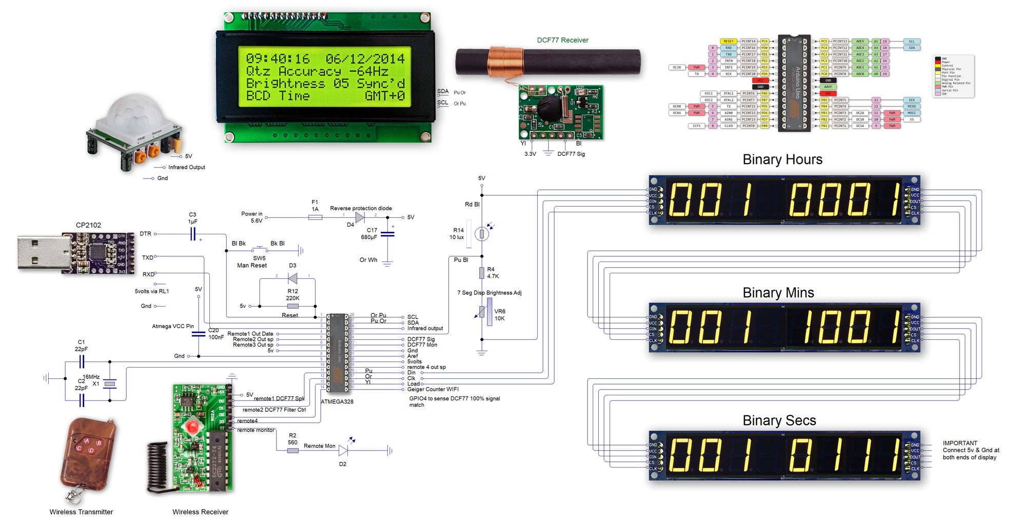
Wiring for this clock is very straight forward as the display modules come assembled. Fit header plugs to the veroboard to take the three LED modules.
Each 7 segment display module has 6 connections Vcc,Gnd,DOUT,DIN,LOAD & CLK.
Vcc,GND, LOAD and CLK are just wired in the first module from the Arduino then looped out to the next module etc. DIN goes in the first module then DOUT of the first module connects to DIN of the 2nd module etc.
The LCD display just has 4 connections 5v, Gnd from the power rails and SCL and SDA connected to the Arduino.
The USB to CP210K module can be omitted if on board programming of the Arduino is not required. In this case the Arduino will need to be removed then programmed in your development board etc.
The DCF77 receiver may need it's own 3.3v power. You can buy 3.3v modules ready built from ebay.
Attachments

Step 6: Code
Note this clock uses Udo Kleins Release 2 library download here
DCF77 Release 2


