

Introduction: Arduino Binary Alarm Clock

This Instructable will show you how to build an binary alarm clock, with a touch sensor snooze button. This is my first instructable and my first real arduino project, I hope you like it!
I bought an arduino a while back and I think it's really nice, but I haven't really done anything useful with it yet, so now I thought it was time to make a bigger project. I decided to do an alarm clock since my old one is broken.
Here's a video of it in action:
There seems to be some problems with the video embedding, If you can't see the video above, here's a link to it: binary alarm clock
Step 1: What Should Be Done?
To help me organize my thoughts about how I should build the clock I wrote down what I think an alarm clock should be able to do. I then tried to build the clock to meet the requirements.
An alarm clock should be able to:What I used:
- keep time - code
- display time - LEDs 5 for hours, 6 for minutes
- keep an alarm time - code
- let the user set the time - buttons
- let the user set the alarm - buttons
- make noise when the alarm goes off. - speaker
- let the user snooze - touch sensor "button"
- let the user turn on and off the alarm. - touch sensor "button"
It would be nice if it also:
- looks reasonably good - a nice box as case
- is cool and geeky - true binary display
Step 2: What You Need.


Parts:
For the display:
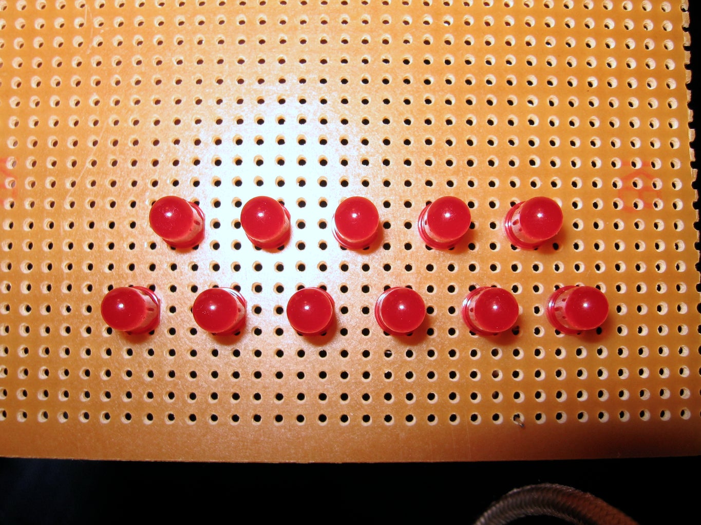
- 11 LEDs
- 11 1kΩ resistors ( don't need to be exact, anything between 300 and 2k should work (a lower value will give brighter light)
- Perfboard (I used perfboard with separate solderpads for each hole)
For sound:
- 1 Speaker (piezo or ordinary, if you use an ordinary speaker put a 1kΩ resistor in series with it)
For time and alarm setting:
- 2 Buttons (Hour button and Minute button).
- 1 Switch for changing between setting the time and setting the alarm.
- A piece of thin plywood.
For the touch sensor:
- Aluminum foil, or even better aluminum tape.
- Tape or glue to attach the foil.
- Paper in the same color as the box to hide the sensor
- Glue for the paper.
- 1MΩ resistor (you can play with this value a bit, depending on how thick your box is, a higher
value gives a more sensitive sensor (it will also make it a bit slower).
For everything:
- Hookup wire (solid core wire)
- Electrical tape
- Solder
- A box to put everything in.
Tools:
- A soldering iron
- Wirecutter and wirestripper
- Drill, or something else to make holes in the case for buttons.
- Saw
Not a must, but good to have:
- A multimeter, for testing connections, etc.
- A solderless breadboard can be good to have to be able to test stuff easily.
- Header pins for connecting the wires to the arduino. I didn't have this and had some problems at first with getting good contact in the connections to the arduino at first, I solved it by securing the connections with tape.
Step 3: Code Structure


I have divided the code for the clock into functions, one for each important bit of functionality. The functions are in separate tabs in the sketch. these are then run in the main loop:
void loop()
{
clock(); // keep track of time, i.e. update hours, minutes and seconds variables as needed.
display(); // display the time, or the alarm time, depending on the state of the settings switch.
alarm(); // checks if it's time for the alarm to start.
update_buttons_state(); // checks if the buttons and touch sensor states has changed
buttons(); // does what the buttons should do
}
The variables that are needed by several functions are declared in the first tab (where setup() and loop() is) and the variables that are needed only by one function is declared in the same tab as that function.
If you change the DEBUG constant to 1 you will get some output via serial that can be good for troubleshooting, e.g. the time and what value the touchsensor returns.
I have tried to comment and make the code understandable but if you have questions or suggestions for improvements just leave a comment.
Here are the pins I used for the different parts:
- 2 and 4: Touchsensor (4 is the send pin, 2 is recieve)
- 6 Hour button
- 5 Minute button
- 7 Switch
- 14-18 Display hour pins
- 8-13 Display minute pins
You can use whatever pins you want, just change in the code accordingly.
Step 4: Time Keeping
To keep track of time I used only the arduino, and the standard arduino function millis(). This method won't be completely exact, because the 16Mhz crystal oscillator, that decides the clock frequency of the arduinos CPU, probably won't be exactly 16 000 000 Hz. The good news is that you can measure how inexact your clock is and compensate for it in your code, because the offset should be constant for a given period of time.
Measure how inexact your arduino is:
As said earlier, the arduino will have a small time error, this error depends on the crystal oscillator and will be different for every arduino, to measure how much my arduino clock differed from the correct time, I programmed it to print out the time ( the hour, minute and second variables) via serial. I then let it run for a long time (Over night and more) and compared the arduino time with a clock I knew was exact, at the start and the end of my measuring period. Divide the time difference with the time the test took to calculate the error each hour. I found that my arduino is about 0.4 seconds to fast every hour. I used exacttimenow.com to get exact time, but if you have a watch you know is very exact, feel free to use that instead.
The code I used to keep the time is an adaptation of some code I found on the arduino forums. I rewrote it with if-statements instead of division and modulo, to see if there would be any speed difference and found that the if-version is more than 15 times faster (although both are still quite fast, more info about the test here).
Since I want the other stuff in my main loop (like checking the touch sensor, checking for button presses, etc.) to happen as often as possible, I used the faster version.
The code:
Every time the clock function is called it adds the time in milliseconds since last it was called to a variable m, when one second has passed (m>999) the second variable is increased by one and m is reset. When the seconds variable reaches 60, the minute variable will be increased by one, and seconds will be set to zero. The same thing happens with the minutes variable; when it reaches 60, add 1 to hours and reset minutes. The hour variable will be reset when it reaches 24.
To compensate that my arduino is 0.4 seconds faster evey hour, I decrease the seconds with two seconds every fifth hour.
____________________________________________________________________
The clock() function:

// CLOCK VARIABLES:
#define MAX_MILLIS_VALUE 34359738
unsigned long current_millis_value = 0;
unsigned long previous_millis_value = 0;
unsigned long m = 0;
int seconds = 0;
int minutes = 0;
int hours = 0;

void clock()
{
  current_millis_value = millis();
  if (current_millis_value < previous_millis_value) // if millis overflows
  {
    m += MAX_MILLIS_VALUE - previous_millis_value + current_millis_value;
  }
  else // if millis has not overflown
  {
    m += current_millis_value - previous_millis_value;
  }
  if (m>999)
  {
    seconds++;
    m = m-1000;
  }
  if (seconds>59) // if seconds == 60
  {
    minutes++;
    seconds = 0;
  }
  if (minutes>59) // if minutes == 60
  {
    hours++;
    minutes = 0;
    if(hours%5==0) // adjust the time with -2 seconds every 5th hour.
      seconds = seconds - 2;  // this will cause seconds to be -2,
                             // therefore seconds can't be unsigned.
  }
  if (hours>23) // if hours == 24
  {
    hours = 0;
  }

  previous_millis_value = current_millis_value;
}
______________________________________________________________________
Step 5: Reading the Display


Most binary clocks I've seen uses binary coded decimals (BCD), which means that each didgit is represented in binary separately. But I chose to use true binary representation, mostly because I think it's cooler with real binary, but also because it requires less LEDs, and therefore less pins on the arduino.
The clock uses 24-hour notation.
In the picture below you can see how the display shoud be read. Just add togheter the values of the lit LEDs to get the time. The second picture in this step has some examples.
Step 6: Building the Display


This will be easier to follow if you look directly on the pictures instead. All text below is in the image notes too.
1. put the LEDs on a piece of perf-board. Remember that LEDs has polarty (long lead should be connected to positive, short lead to ground (negative)), so put all the LEDs the same way to make it easier later.
2. Bend all short leads towards the middle.
3. Take a piece of wire and strip off the insulation a couple of centimeters, fasten it in the perfboard and put it over the short leads. This wire will later be connected to the arduino so don't make it to short.
4. Solder the short leads to the perfboard and to the wire. Clip off the short leads.
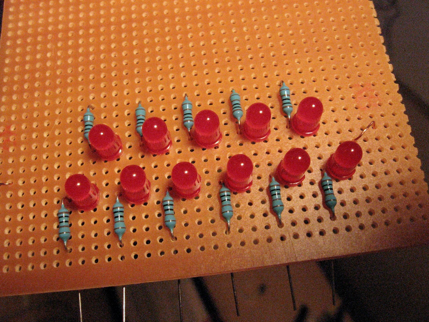
5. add the 11 1kΩ resistors. One of the leads of each resistor should be next to the long leg of a LED.
6. Solder the resistors to the long leads of the LEDs and clip off the excess leads.
7. Attatch wires to the perfboard next to each of the unsoldered resistor leads, and solder them togheter. these wires will be attatched to the arduinos pins.
8. Bind the the wires togheter with cable ties, tape or by wrapping wirepieces around the wires.
I used tape to keep the wires togheter. It's not ideal for getting a good connection to put the wires directly in to the arduino, but it worked ok for me. If you have a row of headerpins, solder the wires to that and use it instead.
Step 7: The Display Code
The display() function works by checking if the hours variable can be divided by 16, if it can, it will turn on the LED representing 16, else turn it off. Then try dividing the remainder of the previous division with 8, turn the 8-led on if it could be divided, else off, divide the remainder of that division with 4 and so on.The same process is then repeated for minutes but starting at 32 instead of 16.
display() uses the hours_p and minutes_p pointers, that points to either the variables hours and minutes, or to the variables alarm_hours and alarm_minutes. What they are pointing to is decided in the settings switch code (in the buttons() function). So when the switch is turned to A (alarm), the display will automatically show the alarm time, and when it's turned back to T (time) the current time will be shown.
____________________________________________________________________
The display() function:
// "INTERNAL" VARIABLES FOR DISPLAY FUNCTION:
int remainder;
int led_value;
void display()
{
// display() will display the ordinary time or the alarm time,
// depending on what hours_p points to, this is decided
// by the settings_switch_state, in the buttons() function
// Display hours:
remainder = *hours_p;
for(int i = 0; i < 5; i++) // repeat four all five hour-LEDs
{
led_value = 16/round(pow(2,i)); // first LED = 16, second = 8, third = 4 etc.
if(remainder/led_value == 1)
digitalWrite(hour_pins[i], HIGH);
else
digitalWrite(hour_pins[i], LOW);
// the remainder of the hours is saved for
// the next LED that is displaying a lower value
remainder=remainder%led_value;
}
// Display minutes:
remainder = *minutes_p;
for(int i = 0; i < 6; i++) // repeat for all six minute-LEDs
{
led_value = 32/round(pow(2,i)); // first 32, then 16, then 8 etc.
if(remainder/led_value == 1)
digitalWrite(minute_pins[i], HIGH);
else
digitalWrite(minute_pins[i], LOW);
// the remainder of the minutes is saved for
// the next LED that is displaying a lower value
remainder=remainder%led_value;
}
}
____________________________________________________________________
Step 8: The Snooze Touch Sensor


The principle behind the touch sensor is quite simple. It uses two pins; a send pin and a recieve pin. A resistor connects the two pins, and something conductive, e.g a piece of aluminum foil, is connected to the recieve pin. The foil will work as a capacitor
When the send pin toggles state, the recieve pin will also, but with a slight delay, depending on the size of the resistor and the capacitor. If something conductive, e.g your hand, comes close to the foil the capacitence will change. This will cause the delay to also change, so by measuring the delay you will know if something is close to the sensor.
There's a good library that does all this measuring for you, called CapSense, written by Paul Badger. Info about the library and a better explanation of how the sensors work can be found here: CapSense library
Building the touch sensor:
1. Attach the aluminium tape or foil on the inside of the box lid.
2. Strip of the insulation from the end of a wire and tape it to the aluminum.
3. solder a 1 MΩ resistor to the other side of the wire. (The value of the resistor isn't critical, but has to be fairly high, just try with what you have handy and see if it works )
4. Cut out a piece of paper that covers the inside of the lid.
5. Glue the paper over the aluminum foil.
Step 9: The Setting Buttons Panel


For setting the time I used two buttons, one for setting hours and one for minutes, and one switch for changing between setting the clock and the alarm.
Building the button panel:
My box had a elevation in the middle that the panel could rest on. If your box don't, you can use four wooden sticks or strips taped/glued in the corners of the box and let the panel rest on those.
1. Measure the inside of your box to see how big you should make the panel.
2. Saw out the panel from a piece of thin plywood. To get a good fit, make the panel a bit bigger
than the inside off the box and sand off the edges until it fits.
3. Cover the board with masking tape and measure out and mark where you want the holes
for the buttons to be. The tape will help to prevent the edges of the hole to splinter.
4. Carefully remove the tape.
5. Attach the buttons and solder wires to them.
6. Make button labels. I used letters cut out in electrical tape.
7.First attatch the tape to something flat that you are not afraid of scratching.
8. Cut out the letters with an utility or exacto knife.
9. Carefully remove the letters.
10. Attach the letters to the panel.
If you can get hold of letraset transfer sheets I think that could work even better.
Step 10: Button and Sensor Code
The code handling the buttons, the switch and the touch sensor is divided into two functions, one for checking if the buttons are pressed and one for doing what the buttons should do if they are pressed i.e. setting the time, setting the alarm, snooze and activate or deactivate the alarm.
I first wrote the code with debouncing for the buttons, but later when I tested my buttons I noticed that I didn't seem to need it, so I removed the debouncing to get less and easier to read code, however I included the function with debouncing in the tab f_comments_etc in the sketch.
Check for button presses:
The code that checks if the buttons are pressed are really simple. It just reads the state of the buttons pins. The arduinos internal pullup resistors are used so the buttons states are HIGH when they are not pressed and LOW when they are pressed.
The touch sensor is read with help of the CapSense library: touch_sensor.capSense(10) this will measure the capacitance 10 times and return an average. Depending on the value returned the snooze_button_state variable will be set to either HIGH or LOW. I have found that when I rest my hand on the lid of the clock i will get a value around 150 and with no hand about 30 ( if I recall correctly). so I used 100 as the limit to change the state of the snooze-"button". Change the value as needed.
______________________________________________________________________
The function that checks for button presses:
void update_buttons_state()
{
hour_button_state = digitalRead(hour_button_pin);
minute_button_state = digitalRead(minute_button_pin);
setting_switch_state = digitalRead(setting_switch_pin);
/* Read the snooze touch sensor: */
if(touch_sensor.capSense(10) > 100) // adjust this value if needed
snooze_button_state = LOW;
else
snooze_button_state = HIGH;
// the if-else above I think could be written shorter as:
// snooze_button_state = (touch_sensor.capSense(10) > 100) ? LOW : HIGH;
}
______________________________________________________________________
Do things if the buttons are pressed:
The settings switch will change the two pointers hours_p and minutes_p to point to either the variables hours and minutes, or alarm_hours and alarm_minutes. The code for the hour and minute buttons will use these pointers, so when the switch changes they will automatically set the right thing; alarm or time. The display function also uses the hours_p and minutes_p pointers so when the settings switch is on alarm, the alarm time is shown.
The hour and minute buttons increase the hours and minutes by one each time they are pressed.
The snooze button will turn off the alarm signal, and set a snooze off time (current time + 10 minutes) when the signal should start again. it also sets the variable snooze_on to true, this will cause the alarm function to start to check for when the snooze of time is.
If the snooze button is held down for 3 seconds it will toggle the alarm off or on. A high pitched tone is played when the alarm is turned on and a low pitched tone is played when the alarm is turned off.
______________________________________________________________________
The buttons function:
// "INTERNAL" VARIABLES FOR BUTTONS FUNCTION:
boolean first_time_hour = true; // these are used to make sure that the hours
boolean first_time_minute = true; // and minutes only is increased once every keypress.
unsigned long snooze_button_timer; // used to keep track of how long the snooze button has
// been held down. when the button has been held down
// a certain amount of time, the alarm will be turned
// of completely.
void buttons()
{
// LOW == button pressed
// HIGH == button released
// (this is because pullup resistors is used)
// Decide if we should set time or alarm:
// (this also makes the display show the alarm time)
if(setting_switch_state==LOW) // LOW = Set time
{
hours_p = &hours;
minutes_p = &minutes;
}
else // HIGH = Set alarm
{
hours_p = &alarm_hours;
minutes_p = &alarm_minutes;
}
// If hour button is pressed, increase hours:
if(hour_button_state==LOW && first_time_hour) // only increase the hours once
{ // every button press.
if(*hours_p < 23)
(*hours_p)++;
else
*hours_p = 0;
first_time_hour = false;
if(DEBUG)
{
Serial.println("hour increase");
Serial.println(hour_button_state);
}
}
else if(hour_button_state==HIGH)
{
first_time_hour = true; // reset when button is released,
} // so that the next press will be registerd.
// If minute button is pressed, increase minutes:
if(minute_button_state==LOW && first_time_minute) // only increase the minutes
{ // once every button press.
if(*minutes_p < 59)
(*minutes_p)++;
else
*minutes_p = 0;
first_time_minute = false;
}
else if(minute_button_state==HIGH)
{
first_time_minute = true; // reset when button is released,
} // so that the next press will be registerd.
if(snooze_button_state==LOW)
{
if(signal_on)
{
// set the time when the alarm signal will start again,
// this will give 10 minutes snooze:
if(minutes<50)
{
snooze_off_minutes = minutes+10;
snooze_off_hours = hours;
}
else
{
snooze_off_minutes = minutes - 50;
snooze_off_hours = hours + 1;
}
snooze_on = true;
signal_on = false;
}
// if the snooze button has been held down for more than 3 seconds turn off/on the alarm
if((millis() - snooze_button_timer) > 3000)
{
if(alarm_on) // if on, turn off
{
signal_on = false;
alarm_on = false;
// play tone so the user know the alarm turned off:
tone_maker.play(NOTE_A3, 100);
}
else if(alarm_on==false) // if off, turn on
{
alarm_on = true;
// play tone so the user know the alarm turned off:
tone_maker.play(NOTE_A7, 100);
}
//reset the snooze button timer
snooze_button_timer=millis();
}
}
else
{
//reset the snooze button timer
snooze_button_timer=millis();
}
}
___________________________________________________________________
Step 11: Alarm and Snooze Code
If the alarm is active (alarm_on variable is set to true), the alarm() function will check if the current time is the same as the set alarm time. If it is, the signal_on variable will be set to true. If the signal_on variable is true, the function will call the play_melody() function.
If snooze is active, the alarm function will also check if the current time is the same as the snooze off time, and if so, restart the alarm signal.
____________________________________________________________________
The alarm() function:
// "INTERNAL" VARIABLES FOR ALARM FUNCTION:
boolean first_time_signal_on = true; // used to make shure the signal is
// only started once, so that you can
// snooze without the alarm starting again
// imidiately.
void alarm()
{
if(alarm_on)
{
// Check if the time is same as alarm time:
if(hours==alarm_hours && minutes==alarm_minutes && first_time_signal_on)
{
// if so, turn on the alarm signal:
signal_on = true;
first_time_signal_on = false;
}
if(signal_on)
{
play_melody();
}
// look in buttons() for snooze button and alarm off button
if(snooze_on)
{
// Check if the time is same as snooze off time:
if(hours==snooze_off_hours && minutes==snooze_off_minutes)
{
// if so, turn off snooze and restart alarm signal:
snooze_on = false;
signal_on = true;
}
}
}
else
{
// reset so that the alarm will work next time:
first_time_signal_on = true;
}
}
_____________________________________________________________________
Step 12: Alarm Signal
It's quite easy to generate sound on the arduino by just using digitalWrite() and delay() to toggle the state of the speaker pin in the right frequency. But for this project I need to constantly check the buttons, update the clock and update the display, even when the alarm signal is playing. Therefore the sound generation has to be non-blocking, which means you don't have to wait for the tones to end before you can do anything else.
Therefore I used the Tone library written by Brett Hagman to generate sound. It's a really nice library which makes it easy to play different tones, and best of all, it's non-blocking.
Because the the melody should be non-blocking I couldn't just use a for-loop to loop through the tones. Instead I used if-statements. everytime the melody function is called it checks if the last tone has stopped playing, if it has it will start the next one. The "melody" I've used is just C, D, E, F, G, A, B, C first played one after eachother, then every other, then every third, and so on.
_______________________________________________________________________
The play_melody() function:
// "INTERNAL" VARIABLES FOR PLAY_MELODY FUNCTION:
int melody[] = { NOTE_C4, NOTE_D4, NOTE_E4, NOTE_F4,
NOTE_G4, NOTE_A4, NOTE_B4, NOTE_C5 };
int melody_length = sizeof(melody) / 2; // Melody length, for looping.
// sizeof() returns the size of the array in bytes, and because
// an int is 2 bytes, sizeof will return 2*(number of array elements)
int i = 0; //loop variable
boolean reset_loop = true;
int jump = 1; // how many notes to jump in the melody array
int position = 0; // position in melody array
void play_melody()
{
if(!(tone_maker.isPlaying())) // if the last tone has stopped
{
if(i {
//tone_maker.stop();
tone_maker.play(melody[position], 300);
// A pause between notes...
//delay(300); // replace with nonblocking.
if (DEBUG)
{ // If debugging, report loop, tone, beat, and duration
Serial.print(position);
Serial.print(":");
Serial.print(melody[position]);
Serial.print("\n");
}
position += jump;
//if position is bigger than the array, start from beginning of array:
position = position%melody_length;
i++;
}
else
{
jump++;
i = 0;
}
}
}
_______________________________________________________________________
Step 13: Upload the Arduino Sketch.
Make shure you have the CapSense Library and the Tone Library, they can be downloaded here, and here.
Unzip and place the folders in the folder libraries in your sketchbook folder.
Download the binary clock source code attached to this step, unzip it, and place the folder in your sketchbook folder too. Plug in your arduino, open the binary_clock_v1 sketch and press the upload button.
If you've done everything right you should now have a working binary alarm clock! If something seems wrong, double check all conections. Is everything connected? Is everything connected to the right pin?
Attachments

Step 14: Put Everything in the Box


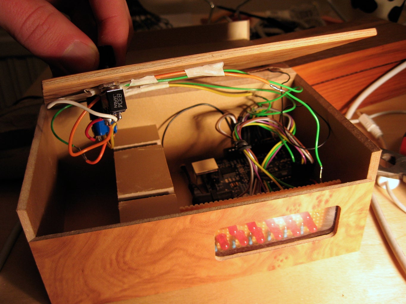


When you've made shure everything works as it should, you are ready to put everything into your box.
The box I used already had a window in it so I didn't have to make one. If your box don't have a window, drill four holes where you want the corners of your windows and the use a small saw, and saw between the holes. Then sand the edges.
Drill a hole in the backside of the box for the power cord. To be able to make the hole small, cut off the cord near the wallwart, where it won't be noticed, put it through the hole and then tape it togheter again with electrical tape.
If you like me didn't use header pins to connect all your wires I highly recommend you to secure all wires to the arduino with tape before you try to put the arduino into the box.
If you have an diecemilla or older arduino, remeber to change the power jumper to external power.
Step 15: Ideas for Improvement
Since I would want to use my arduino for other projects later and since tape isn't the ultimate way to attach wires, maybe I will do a separate circuitboard with an atmega with the arduino bootloader. The clock works good as it is however so we'll see when I find the time to do that. Another improvement would be to make the usb port easier to reach for when you want to update the code.
Step 16: Final Words
Thanks for reading! This has been a really fun project to make and I've learned a lot. I hope you enjoyed reading the instructable and that the instructions where clear.
If you have any questions just ask.
Second Prize in the
Arduino Contest


