

Introduction: Arduino "Blink to Talk" Using Charlieplexing


This project can be classified as an AAC (Alternative and Augmentative Communication) device, which are used as a means of communication for those suffering from debilitating diseases like ALS and the like, that result in complete paralysis and near-total loss of body function. The device we shall build in the course of this instructable, enables a patient to communicate with people merely by blinking their eyes.
Innumerable devices already exist along similar lines, even commercially, and now at a fraction of the price that they once were. However, even now, those prices continue to be far out of the reach of the vast majority of individuals suffering from said diseases. Brilliant projects like the Eyewriter, have made it incredibly cost-effective to achieve the same results as commercial solutions. Information about the Eyewriter can be found here:
However, this project came about because of the primary flaw that I observed in the eyewriter. A flaw, that granted, is not relevant in many parts of the world. The dependency of the Eyewriter on an uninterrupted power supply, as well as the availability of a computer, may seem like a bare necessity, but this puts it out of the reach of many millions of people.
Thus, I conceived the idea for an extremely low-cost device, that would consume an incredibly small amount of power. Now, I must warn you, that the functionality of this device is limited, and absolutely does not even compare to the eyewriter. But I hope that the concept behind it, might lead to better, cheaper, and more accessible ideas in the future.
There's a demo attached to this section. of the device being used to type out a simple word and a phrase. I'd suggest watching it before going any further since it'll make what comes ahead a lot easier to understand. The glasses haven't been worn because of the difficulty I faced in filming both the blinking mechanism, and the device at the same time. Instead, I have covered the sensor when required to simulate a blink.
Step 1: Working


The functionality is simple. The sensor consists of an IR-LED/Photodiode pair mounted on a pair of glasses. The value returned by the photodiode varies depending on whether the IR light is reflected off of the eyelid or the white sclera of the eye. This is used to obtain threshold values for the blink detection.
Now, to be able to individually address 26 LEDs for each of the 26 Alphabets, I'd need 26 I/O lines. To keep costs low, I wanted to use an ATmega328, rather than the ATmega2560 which would have more than sufficient IO lines for our purpose. However, the ATmega328 falls short by a lot. To fix this, we fall back on a rather interesting method of multiplexing called Charlieplexing. It works like this. The 30 LEDs are connected in a grid as shown in the attached grid schematic. A quick look would tell you that by turning on any two lines, a whole lot of LEDs are going to light up when we want just one of them to light up. This is accomplished by turning on two lines, while putting all the other 4 lines in a High Impedance State, which for an Arduino, would mean declaring those 4 lines as INPUT lines. It'll be easier to understand if you study the image for a while, while paying close attention to the polarity of the LEDs. For more information on Charlieplexing, you can find an excellent instructable on Charlieplexing Theory here.
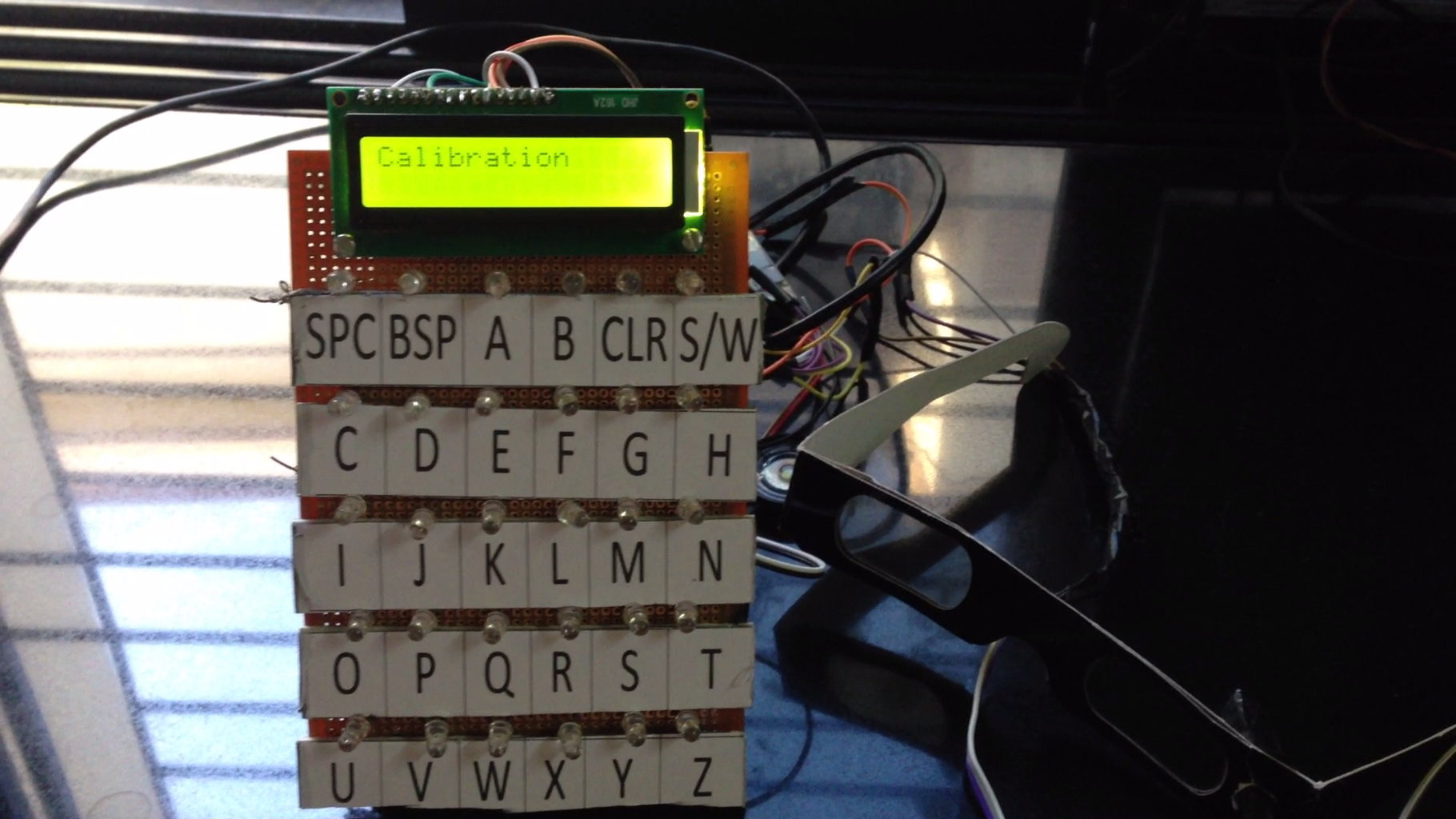
Now, the LED grid works exactly like an Alphabet Board used for individuals suffering from ALS. When the system is switched on, a calibration prompt obtains the threshold values by having the user keep his eye open and then closed for a set amount of time. The system then begins scanning each horizontal row of the grid (turning on a row of LEDs) with intervals of 1-2 seconds, all the while checking for a blink. When a blink is detected while a particular row was turned on, the system beings scanning each LED of that row, column by column, while checking for a second blink. When a second blink is detected on a particular alphabet, that alphabet is printed to the LCD, and also optionally transmitted to other displays via the bluetooth module. A toggle switch in the first row, enables the user to type out a common phrase corresponding to each alphabet, rather than typing the whole thing out letter by letter. Optionally, this system also allows the user to control other devices and amenities in the room wirelessly, by transmitting a signal to a second module that is hooked up to a relay. This will be discussed later. I also experimented with having the blink sensor as part of a separate wireless headgear, and will attach the results of it towards the end of this instructable.
Step 2: Material List

- Arduino (Any one that works on the ATmega328, I personally used the Pro Mini)
- 16x2 LCD
- Perfboard
- 30 LEDs
- JY-MCU (HC-04) Bluetooth Module [Optional]
- 433/313 Mhz RF transmitter and Receiver [Optional]
- Soldering Iron, wires, and the like
- TCRT5000 (IR LED and Photodiode Pair)
- Pair of Glasses (I used cheap 3D glasses to avoid having to drill a good pair)
- 4 channel Relay Board [Optional]
- nrf24l01+ 2.4Ghz module x2 [Optional]
- Piezo Speaker [Optional]
Step 3: Fabricating the LED Grid


This should be pretty straightforward if you follow the attached grid schematic. However, it is also extremely messy simply because of the limited area you're going to have to work with, if you use a 4x6 inch perfboard like I have. It's a good idea to test every LED before you begin, because it'll be very difficult to determine if a fault is because of the wiring or otherwise later. You could begin by laying down 6 wires vertically as the vertical columns, and then the horizontal rows while using jumpers when required, and of course, a LOT of insulating tape to prevent shorts.
Screw on the LCD to the top of the perfboard. you could paste on labels for each row from the attached pdf. It's been scaled to an A4 size sheet, so if you print it out to an A4 sheet, you should have labels that are just the right size for a 4"x6" board.
You'll also want to print out the two separate boards listed as 1.pdf and 2.pdf, since they function as a key to the Phrases Toggle in the system.

Step 4: Hooking Up the Arduino


The circuit diagram should make things pretty clear at this point. The 6 LEDs on a perfboard in the diagram are just an indication that those are the 6 lines that need to be hooked up to the LED grid we fabricated earlier. I will be attaching the codes in a later section, so it might be helpful to take a look at them if you need to have any Pin numbers cleared up.
As I've mentioned earlier, I'd also created a wireless relay system that can be controlled by the same device. I'll be briefly talking about that module later, but that is what the 433Mhz transmitter has been connected for, in the circuit diagram.
Additionally, I'd dabbled with making the blink sensor as a separate wearable wireless headgear with its own Arduino and 2.4ghz transmitter, rather than to have it connected to the main module as it is now. Since we're talking about individuals who are going to be restricted in terms of mobility, as well as the fact that the LED Grid should be as near to the user as possible for better visibility, it seemed a lot of trouble for very few gains. However, I will include the code as well instructions on the wireless headgear in a later section just in case you;re interested, since it took an interesting bit of code and and a cascaded Arduino transmitting data via the I2C protocol, to achieve real time interrupts for the blink detection.
Step 5: Fabricating the Eyeglass Frame Blink Sensor
For this, I chose a cheap pair of 3D glasses through which I could eaily pierce the TCRT5000 through and then secured it with insulation tape. You'll want it to be secured in such a way so as to still be flexible, since you'll need to reposition this exactly in front of your eyeball. It'd be a good idea to whip up a small test sketch to find the best position and angle of the sensor on the frame.
Step 6: Burning the Code, and Testing.


Go ahead, and burn the code attached to this section. You'll need the VirtualWire library while compiling, which you can find here.
When you're done, the system should start by saying 'Calibration'. After this it will ask you to open your eyes for 3 seconds followed by to close your eyes for 3 seconds. It will then display the recorded values. the values should be sufficiently distinct so as to allow for feasible detection. I generally got open eye values of about >900 and closed eye values of about <400. If your values are incorrect, you might want to check the wiring, or the sensor itself. It might be easier to try covering the sensor to simulate a blink, rather than actually blinking at this point.
Try out the toggle switch too. From the code you should realize that the first 4 rows correspond to the phrases you'd printed earlier. And the last row consists of an emergency button, an OFF button, and 4 relays that transmit wirelessly to the secondary system we'll build shortly. The emergency switch just flashes the LEDs while emitting a high pitched tone from the Piezo buzzer, while the OFF switch turns off the system for 10 seconds.
If everything works out fine, congratulations! Feel free to build any modifications and improvements that you can think of and then share it with us all as in the comments.
Attachments

Step 7: Building the Optional Wireless Relay System

If you choose to build the relay system as well, al you have to do is hook up a 4 channel relay to another arduino on pins 2, 3, 4 and 5, and the 433Mhz receiver to pin 12. I've attached the code for this Arduino to this section.
Attachments
Step 8: Experimenting With a Wireless Headgear
I tried hooking up the blink sensor to another Arduino Pro Mini which also had an nrf24l01+ transceiver hooked up to it. Ideally this would all be mounted on the eyeglass frame and would then be transmitted to the 'Base Station' arduino, that is, the one with the LED grid attached to it. The base station too, would have an nrf24l01+ transceiver hooked up to it apart from the existing 433Mhz transmitter.
I ran into many problems that involved having the base station arduino simultaneously juggle switching on several LEDs on a row, while also receiving an input from the 2.4Mhz transceiver and then judging whether a blink had occurred. Thus, I decided the best solution was to have a secondary arduino connected to the base station, take care of wirelessly receiving the blink values via the 2.4Ghz transceiver, and then send it to the base station arduino via a wired connection.
I ran into even more problems trying out a serial connection between both Arduinos in the base station, and also with an SPI connection. I was finally successful utilizing the I2C protocol to establish real-time communication between both arduinos, with no delay. The slave arduino simply received the blink value wirelessly and then passed it on to the master Arduino which decided if a blink had occurred or not while handling the lighting of the LED grid.
Naturally, I thought this system was a lot of trouble for almost no benefits, since as I've mentioned earlier, mobility of the user, and proximity of the LED grid are an issue.
However, I have attached an entire set of all 4 codes for each of the 4 arduinos, should someone want to experiment with this concept. The four codes are for:
- The base station master arduino that handles the LED grid
- The base station slave arduino that handles the wireless reception
- The transmitter that is mounted on the headgear with the sensor
- The relay station that receives the 433Mhz signal and switches on a corresponding device


