

Introduction: Arduino CNC


Hi, this is my first instructable and I hope to do more.
This project was for 'Creative Electronics', a Beng Electronics Engineering 4th year module at the University of Málaga, School of Telecommunications.
http://www.etsit.uma.es/
It's a cnc using Arduino UNO R3 , GCode Sender and GRBL. The cnc is made of wood thanks to the help of my father. It has taken us many hours to do the mechanical part however the electronic part is faster to do, but is very gratifying. I based my project on these videos and I have received much support from the author of the first video.
[Reproducir video]
[Reproducir video]
The total cost of the project is about 450€.
Step 1: Materials and Components


From experience I recommend buying all the necessary materials before starting the realization of any project.
Materials and components:
- Laminated Wood
- Screwed Steel rods
- Steel bars
- Ball bearings
- Nuts
- Screws
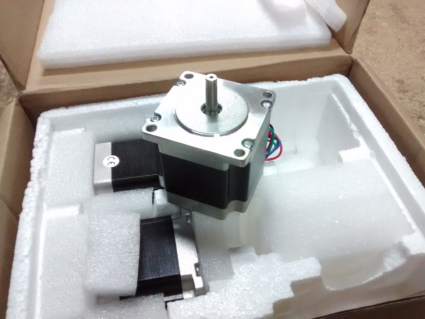
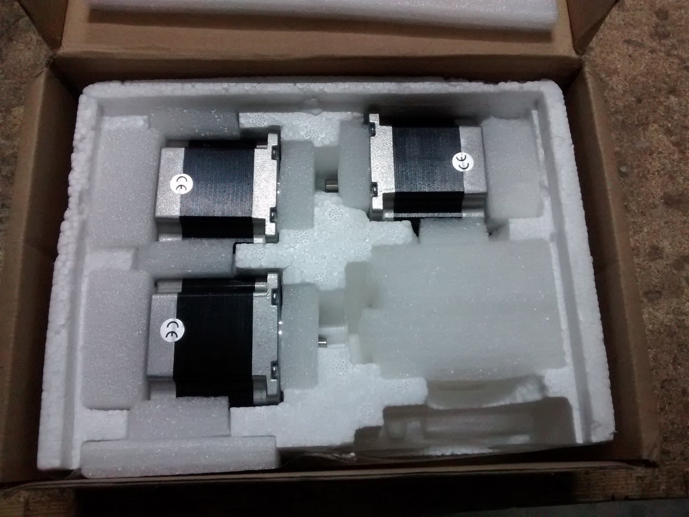
- Stepper motors (in my case Nema 23)
- Stepper motors drivers TB6560
- Switching power supply 24V 15A
- Arduino UNO R3
- Some wires
- Nylon and metal bearings
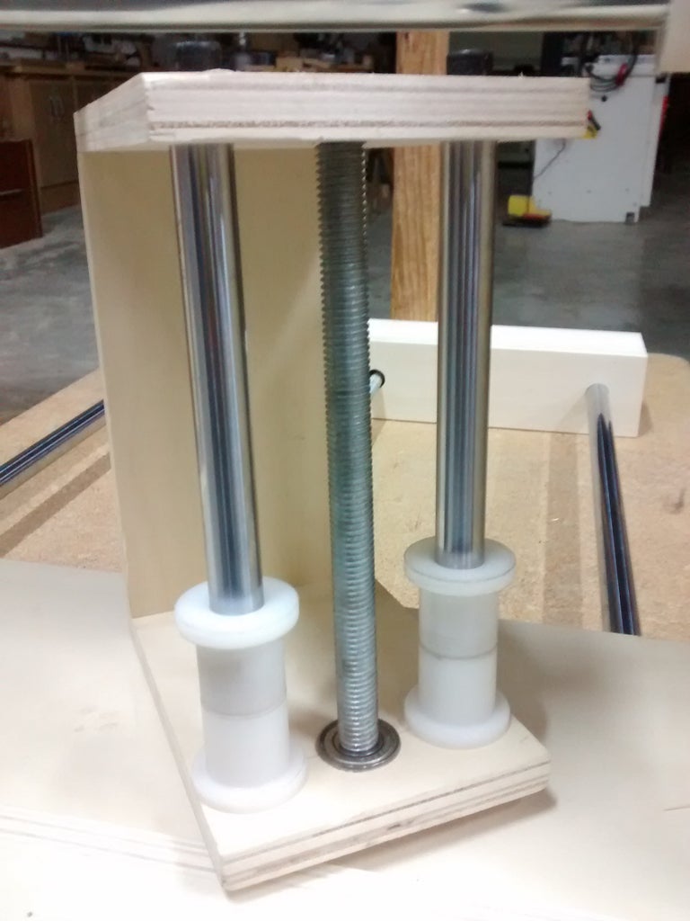
Step 2: X Axis


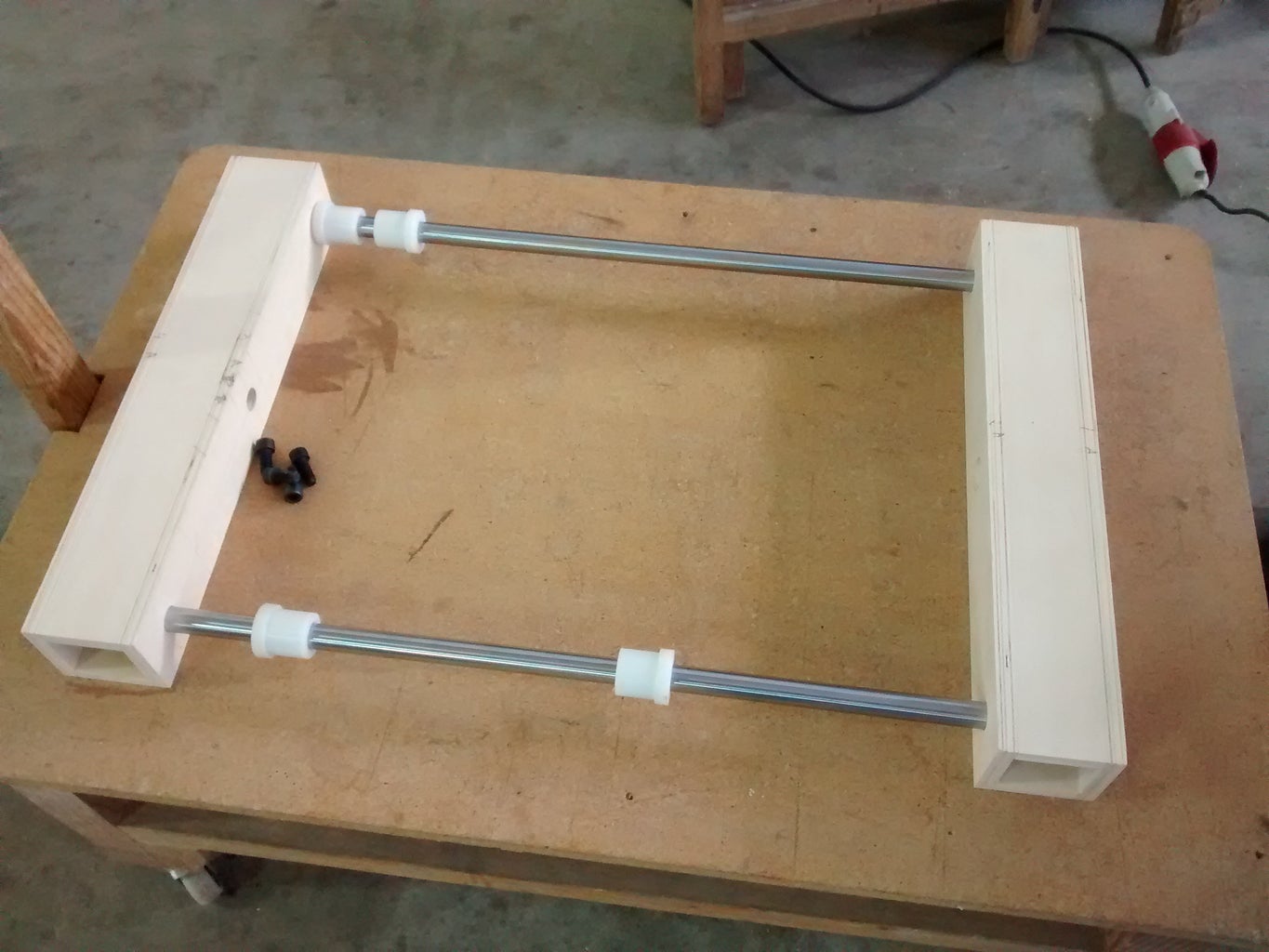

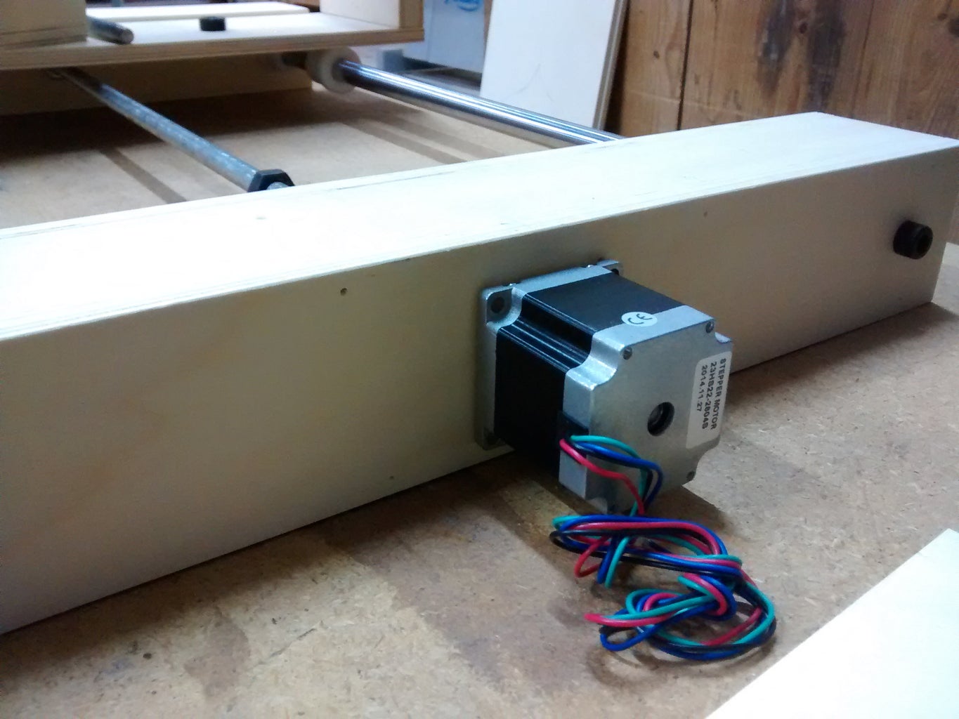
To build the base we have been cut several wooden boards which have made holes and blind holes. These tables form the support of the machine. The screwed steel rods operates as a worm drive. The blind holes serve as a stop for the steel bars that act as guides for the x-axis, in the middle, we put the screwed steel bar, that when turning, generates displacement in the x-axis. Above, we have put a wooden board greater weight and thickness for stability.
Step 3: Y Axis

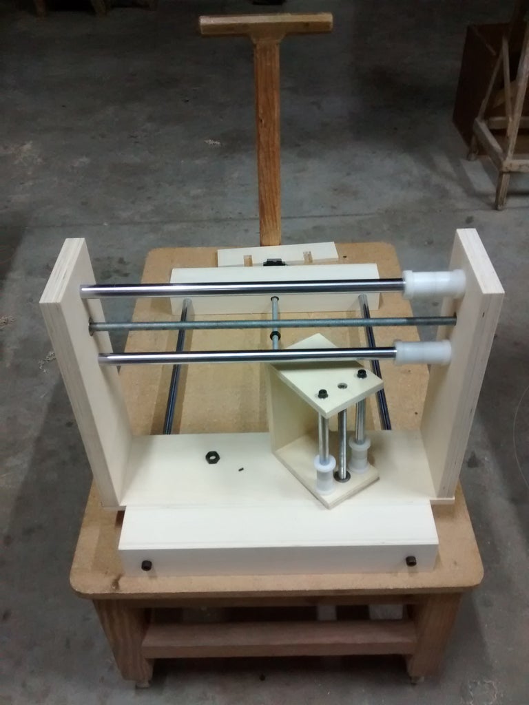


Bridge construction (y-axis) is very similar to that of the base, but this is supported on a table that is moved in the x-axis by a fixed nut below table. You see it at the last picture.
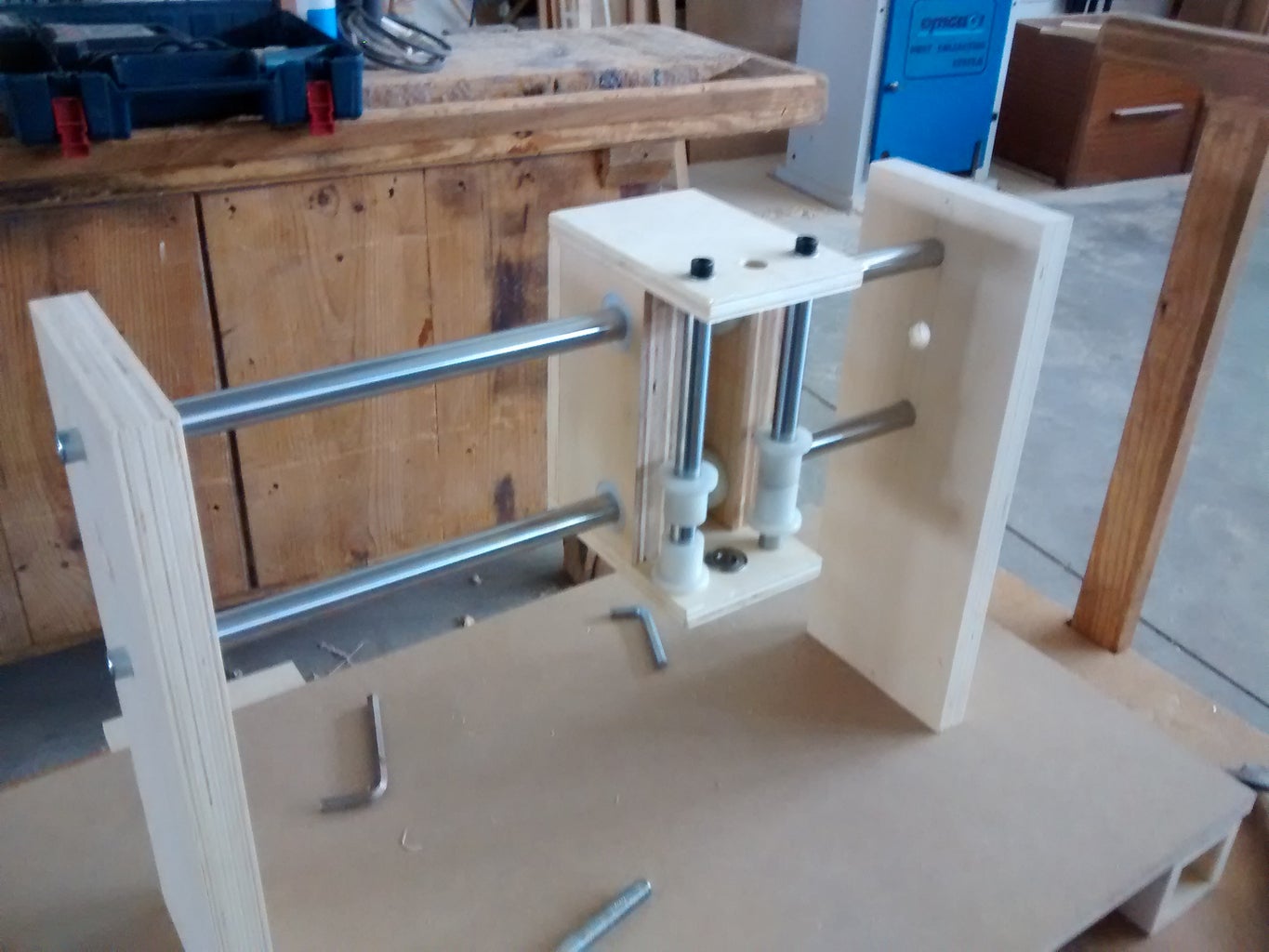
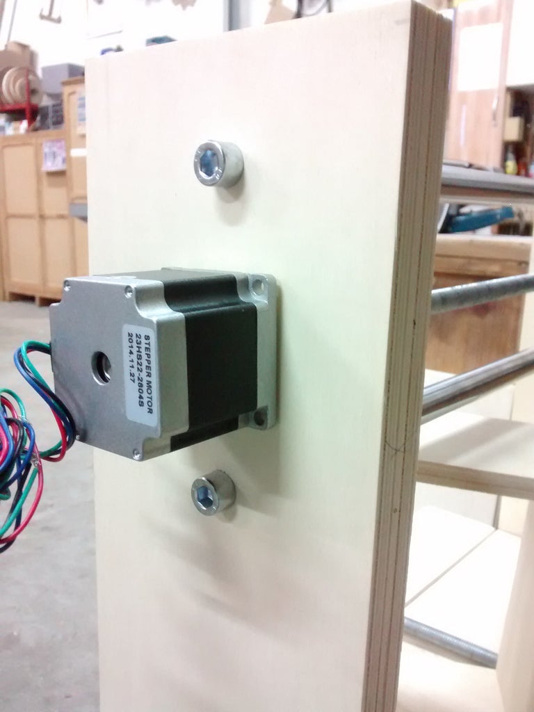
Step 4: Z Axis
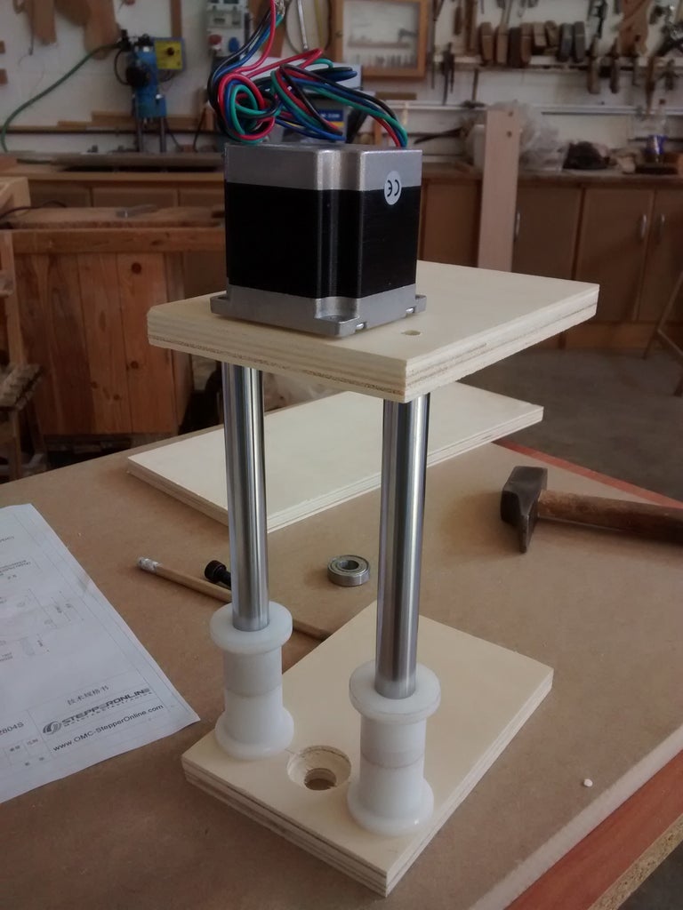
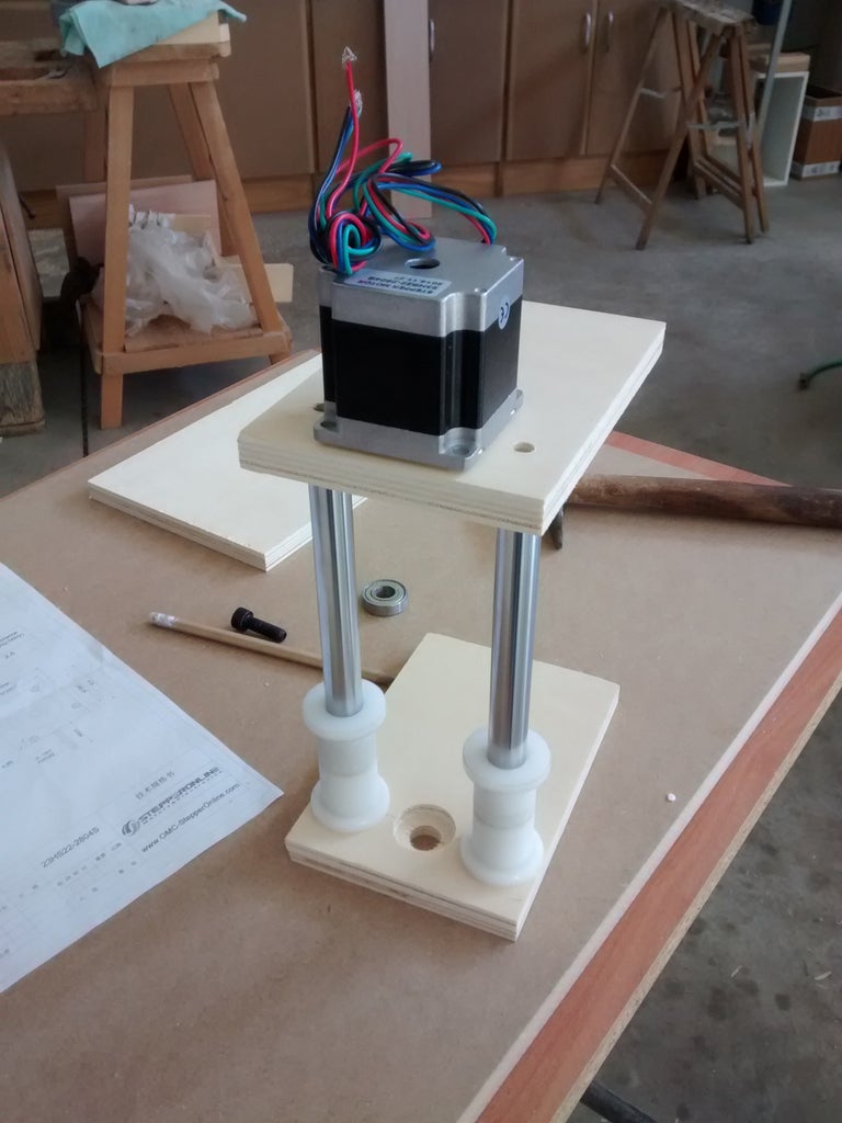


And finally the z-axis, similarly fact that the other two axes and carries a support for a milling or engraving machine. To test I used a screwdriver to move the axis. :)
Step 5: Assembling All of Axes


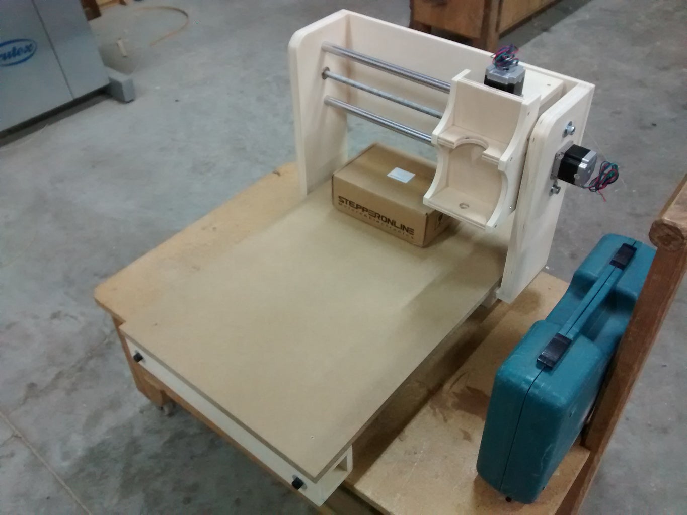

The final assembly is simple with some screws. I have not used glue to replace parts if broken.
Step 6: Electronic Connections


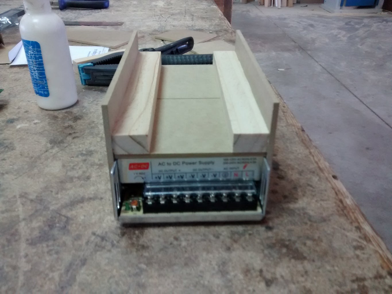
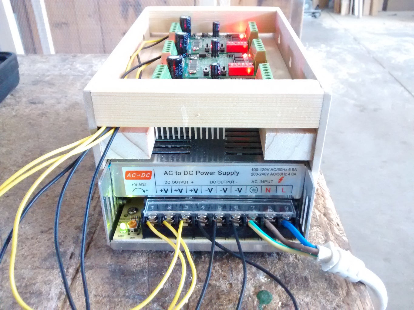
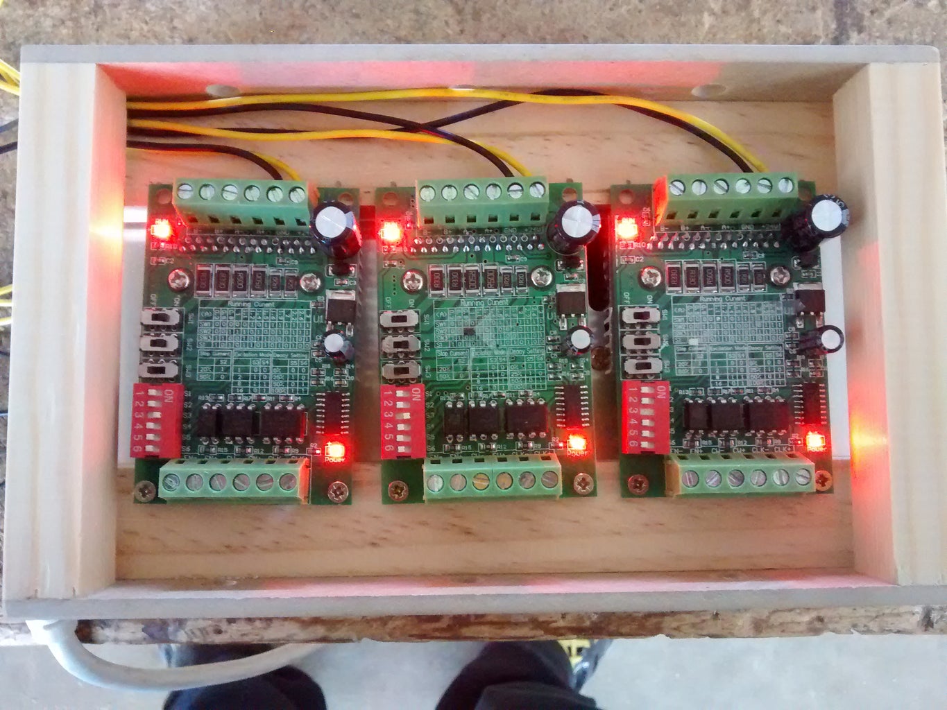
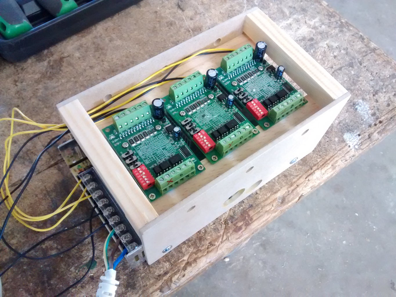
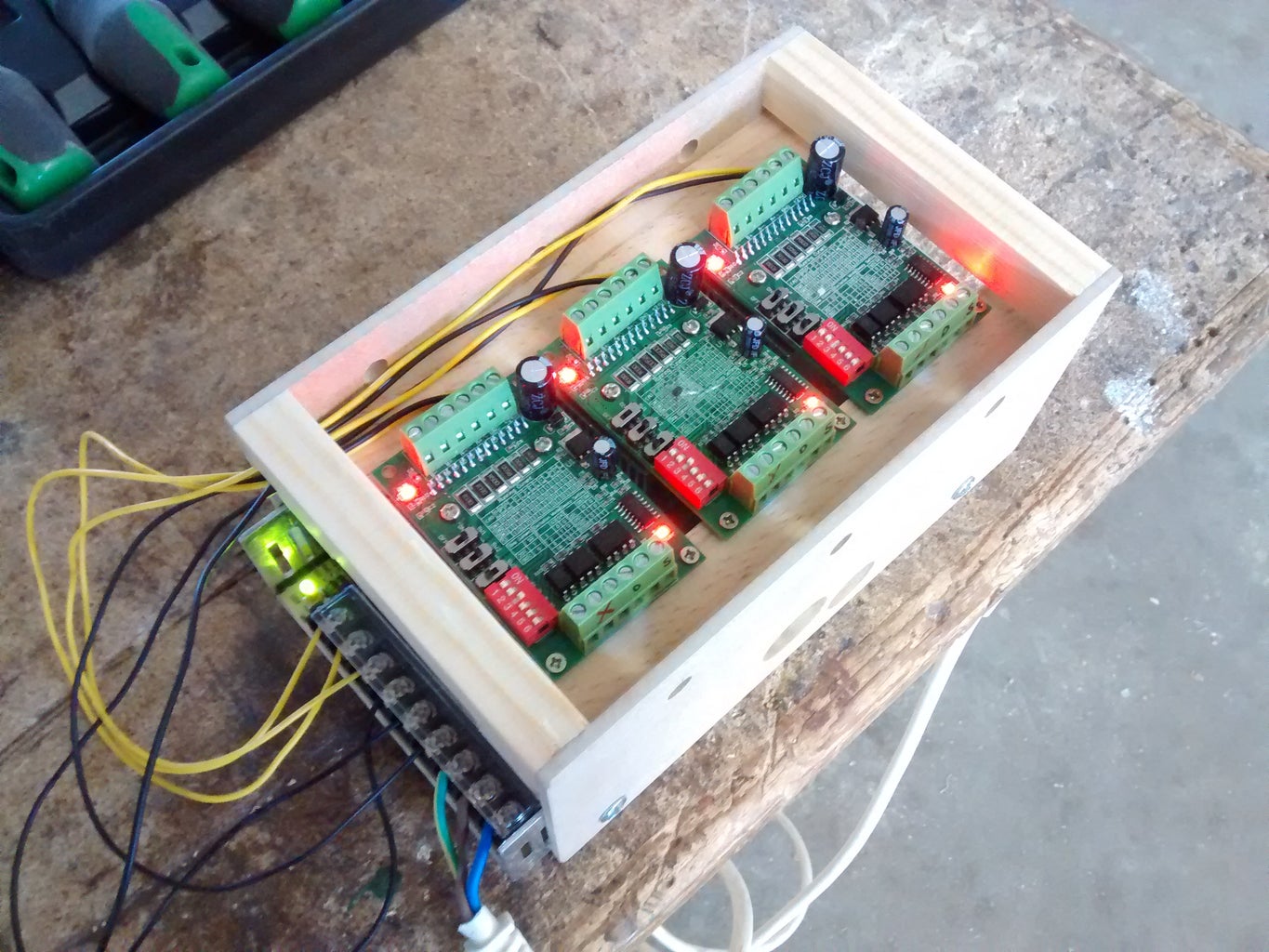


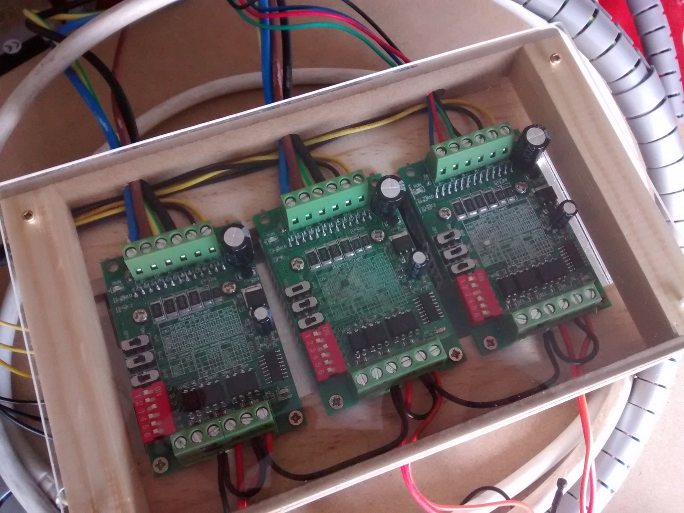
The connectiosn are simple. You need to use one driver for each motor. Each driver need power supply to work. I use a 24V 15A power supply. I select in the drivers my motors amperage. The A+, A-, B+, B- correspond with each of two coils of the motors and his poles. CLK+ (Clock) connects with the step pin on Arduino, CW+ (Clock Wise) connects to direction pin, CLK- and CW- connects to GND pin. EN+ and EN- not need to connect.
In the link below are the Arduino pin diagram of GRBL and some descriptions.
Step 7: Load and Configuration of GRBL on Arduino Uno R3
I see this video to load GRBL on Arduino Uno R3. In the description of this are the links to the programs and files of GRBL. Is very simple. With XLoader load the GRBL code (grbl_v0_8c_atmega328p_16mhz_9600. hex) on your arduino, then open GCodeSender to conect your Arduino to your pc and it's ready to use.
This video explains how to configure GRBL according your stepper motors.
Step 8: Finish
You can use any CAD program to design your projects and CAM programs to machining the GCode for different needs work. I use MasterCam X7 that is CAD and CAM program.
And this is the final result and I hope you like it.
Thanks so much for watch this instructable and enjoy!

Fourth Prize in the
Tools Contest

Grand Prize in the
CNC Challenge


