

Introduction: Arduino Car G-Meter Display


I made this project for my Physics 308L class. It is not yet completed but the whole idea is here for anyone to replicate.
You can create most of these parts from their cheaper components, but I chose to use pre-made parts like the DFrobot LCD shield for Arduino and accelerometers pre-soldered to boards.
This project is a hand held g-meter that constantly outputs acceleration on a screen. It measures the acceleration along three axes (Linear and Lateral g as well a Vertical g), which can be changed between by pressing buttons.
I am planning on using this device in many cars to measure acceleration, calculate real torque put to the wheels, and even estimate real brake horsepower. (It will just be an estimate because the main car I will be using does not have an ECU and therefore I cannot measure real engine RPM.)
Here is a link to my Physics Lab Notebook with more details on what I did:
http://github.com/bmiddl01/Brandon-308L/wiki/_pages
Materials you will need:
- Arduino Uno R3 Microcontroller
- DFrobot LCD shield
- MMA7361 Accelerometer (or any other accelerometer)
- (Car/USB adapter) optional http://figshare.com/articles/Car_USB_adapter_for_arduino_accelerometer/92033
- Cable
Step 1:

Attach your DFrobot LCD shield to your arduino. (Or wire an LCD screen yourself to the microcontroller)
Make sure it works by uploading the following sketch (code for Arduino):
//Sample using LiquidCrystal library
#include <LiquidCrystal.h>
/*******************************************************
This program was originally created by
Mark Bramwell, July 2010
It was then changed for an accelerometer project
by Brandon Middleton, April 2012
********************************************************/
// select the pins used on the LCD panel
LiquidCrystal lcd(8, 9, 4, 5, 6, 7);
// define some values used by the panel and buttons
int lcd_key = 0;
int adc_key_in = 0;
#define btnRIGHT 0
#define btnUP 1
#define btnDOWN 2
#define btnLEFT 3
#define btnSELECT 4
#define btnNONE 5
// read the buttons
int read_LCD_buttons()
{
adc_key_in = analogRead(0); // read the value from the sensor
// my buttons when read are centered at these valies: 0, 144, 329, 504, 741
// we add approx 50 to those values and check to see if we are close
if (adc_key_in > 1000) return btnNONE; // We make this the 1st option for speed reasons since it will be the most likely result
if (adc_key_in < 50) return btnRIGHT;
if (adc_key_in < 195) return btnUP;
if (adc_key_in < 380) return btnDOWN;
if (adc_key_in < 555) return btnLEFT;
if (adc_key_in < 790) return btnSELECT;
return btnNONE; // when all others fail, return this...
}
void setup()
{
lcd.begin(16, 2); // start the library
lcd.setCursor(0,0);
lcd.print("ACCELERATION:"); // print a simple message
}
void loop()
{
lcd.setCursor(0,1); // move to the begining of the second line
lcd_key = read_LCD_buttons(); // read the buttons
switch (lcd_key) // depending on which button was pushed, we perform an action
{
case btnRIGHT:
{
lcd.print("Y-AXIS:.");
lcd.setCursor(8,1); // move cursor to second line "1" and 9 spaces over
lcd.print(analogRead(A2)); // display number between 0-1023 corresponding to voltage
lcd.setCursor(11,1);
lcd.print("g");
delay(300);
break;
}
case btnLEFT:
{
lcd.print("Y-AXIS:.");
lcd.setCursor(8,1); // move cursor to second line "1" and 9 spaces over
lcd.print(analogRead(A2));
lcd.setCursor(11,1);
lcd.print("g");
delay(300);
break;
}
case btnUP:
{
lcd.print("Z-AXIS:.");
lcd.setCursor(8,1); // move cursor to second line "1" and 9 spaces over
lcd.print(analogRead(A1));
lcd.setCursor(11,1);
lcd.print("g");
delay(300);
break;
}
case btnDOWN:
{
lcd.print("Z-AXIS:.");
lcd.setCursor(8,1); // move cursor to second line "1" and 9 spaces over
lcd.print(analogRead(A1) );
lcd.setCursor(11,1);
lcd.print("g");
delay(300);
break;
}
case btnSELECT:
{
lcd.print("PAUSE ");
delay(300);
break;
}
case btnNONE:
{
lcd.print("X-AXIS:.");
lcd.setCursor(8,1); // move cursor to second line "1" and 8 spaces over
lcd.print(analogRead(A3));
lcd.setCursor(11,1);
lcd.print("g");
delay(300);
break;
}
}
}
Step 2:

Attach accelerometer to Arduino.
This is the step I messed up twice!
(note: most accelerometers can only be connected to 3.3V! Luckily there is a 3.3V source on the Arduino Uno r3.)
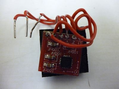
To make the accelerometer more compact I wanted to solder wires directly to the board so I could easily connect them to the shield.
http://figshare.com/articles/ADXL330_accelerometer_w__wires/92034
Accelerometers easily overheat so only touch the soldering iron to the chip for 2 seconds max! I did not realize this and bought a cheap soldering iron which did not get hot at the tip. I had to touch it for long periods of time to solder the wires and I am sure this is what broke my accelerometer (ADXL330 and ADXL335).
I now have ordered an even easier accelerometer: MMA7361 with cable attachments also from DFrobot. This works MUCH better because it has a 3.3V voltage regulator and female adapters that fit pins on the LCD shield. You also do not have to solder with this option.
The other option is very bulky; you can wire the accelerometer on a breadboard to the Arduino.
Outputs on Arduino:
There are three rows of pins on the bottom of the LCD shield (each row has 5 pins)
The top row, marked 5V are each 5V pins.
The second row are all ground pins.
The third and last row is marked S, but they are the Analog outputs of the Arduino. They start on the left with A1 and go through A5. (the A0 pin is used by the LCD shield)
If you need the 3.3V source (for accelerometers without voltage regulators) it is located on the bottom of the shield as a hole. It is directly to the left of the 5V hole. If you are still unsure you can easily tell which one is the 3.3V by removing the shield and it is marked on the Arduino.
If you have the MMA7361 attach each V to a 5V pin, each Gnd to a Ground pin and Z-axis to A1 pin Y-Axis to A2 and X-axis to A3.
If you are using and ADXLxxx accelerometer connect Vs to 3.3V gnd to Ground Z-axis to A1 Y-Axis to A2 and X-axis to A3.
Step 3:

Make a box for your hand-held system.
I made my box out of ultra-pro hard playing card cases and tape.
First I cut out holes in my cases to let the buttons, pins and screen fit through. I made two of these and taped them together to make the face sturdier.
I then cut the other five sides to the right size and taped two cases together per side to strengthen the box.
This was my finished box:
http://figshare.com/articles/Home-made_Arduino_w_LCD_case/92030
I also cut a hole for the charger:
http://figshare.com/articles/Home-made_arduino_with_LCD_shield_case/92029
and these are the materials:
http://figshare.com/articles/Materials_for_Arduino_case/92032
Step 4:
Fine tuning and Calibration.
I have not had the chance to do this step yet because I have not yet received my latest accelerometer. Basically once you have your device reading the Voltages from the A1-A3 analog pins, you have to figure out what your output voltage is from the accelerometer when it measures no acceleration.
The easiest way to do this is to chose one axis at a time and tilt the accelerometer so that axis is either straight up or straight down relative to the ground. Record those voltages and add them together then divide by 2. This is 0g acceleration for your accelerometer. Repeat for the other two axes.
Now take the value when your accelerometer axis was pointing downwards towards the ground (this is 1g accelation) and subtract your zero g value. Take that and divide 1 by it. That is how many g's each value from (0-1023) the analogRead() function is. I will call this value num_per_g in the following code.
Repeat for each axis.
Lastly, in the code in replace analogRead() by:
(analogRead() - (zero_g_val))*(num_per_g)
This will be the fraction of g your accelerometer is measuring.
This works because most accelerometers are ratiometric meaning they output voltages proportionally to the input voltage and the acceleration.
I have not actually done all of this yet so there might be problems.
One possible one is that you might need to use 'float' instead of 'int' in the code for decimals. Another problem that I'm not sure I understand yet is if the numbers 0-1023 will correspond to 5V nomatter what. This would reduce accuracy of accelerometer.
This works because most accelerometers are ratiometric meaning they output voltages proportionally to the input voltage and the acceleration.
(Notice that the numbers the LCD prints from analogRead() is a number between 0-1023. This corresponds to your input voltage (in most cases is 3.3V) with 0 being 0V and 1023 being 3.3V.
It is a good idea to measure your voltage from your arduino pins for more accuracy. (my arduino 3.3V pin produced 3.210V)
You do not really need to know the actual voltage though, most of the time you can use the 0-1023 value since the accelerometer is ratiometric anyway.)
Step 5:
Keep working on your accelerometer and enjoy!
Here is a link to my Physics Lab Notebook for more details of what I did:
http://github.com/bmiddl01/Brandon-308L/wiki/_pages
[torque (low speeds) ~ acceleration(multiply decimal by 32.2ft/sec^2)*(car weight (lbs) * tire radius (ft))/(gear ratio*final drive ratio)]
[HP = torque*(engine RPM)/5252]


