

Introduction: Arduino Commute Checker


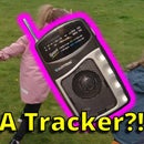

In this Instructable I'll show you how to make an Arduino Commute Checker, a device that uses a ESP8266 to check the fastest way to get home from work! It will light up the fastest route taking into consideration traffic conditions using my Arduino Google Maps library.
Check out the video above for a quick overview of the features.
If traffic on the route is normal the route will light up green, if it is worse than normal it will light up yellow and if it's really bad it will light up red.

There is also a 7-segment display to show how long the journey will take and also to display the time.
It has some really cool ESP8266 libraries installed too, it uses WiFiManager which allows you to configure your WiFi and some extra parameters without re-programming your board.

Displaying that config mode is enabled
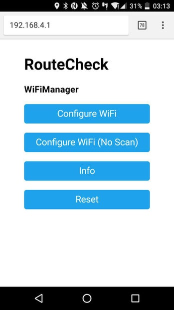
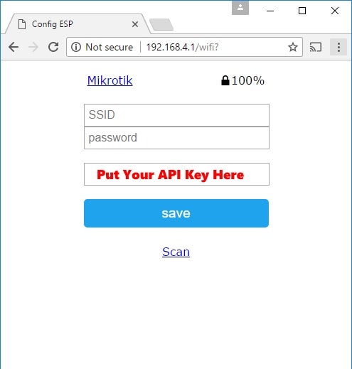
Config Portal for setting WiFi Details
The total cost of this project is about $25 and is a weekend project in terms of time it will take.
I will go through each step for making this project in detail. including how to get a map that suits your commute. You can add or remove as many routes as you want.
Hopefully you find this instructable useful and please let me know if you get stuck at any part of it and I would be more than happy to try help!
Step 1: What You'll Need


When I was designing the project I wanted to keep at simple as possible. There is surprisingly little electronics needed for the project and I wanted to try use only tools that would be common to have or at least easy to get.
Parts List:
- 23cm Ribba picture frame
- Source:Ikea
- Price: $10
- It's a deep picture frame. It's only E5 in Europe :)
- Wemos D1 Mini
- Source:Aliexpress
- Price: $2.80
- Any ESP8266 development board should do (NodeMCU, Adafruit Feather Huzzah esp8266 etc). The D1 mini does come with pin headers that I use in the project later
- A bunch of 5mm PL9823
- Source:Aliexpress
- Price: $6.60 for 20
- These are basically the same as Neopixels, they even work with the Neopixel libraries. The amount you will need will vary for your project based on your map
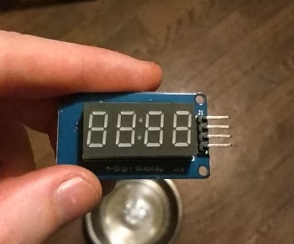
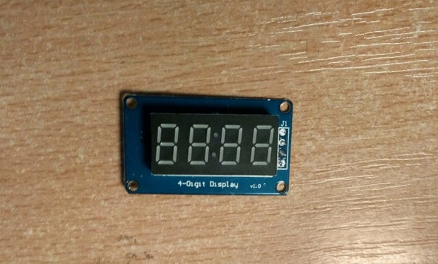
- A 4 digit 7 segment display
- Source:Aliexpress
- Price: $1.30
- It uses the TM1637 chip, this one has double dots in the middle.
- 220uF capacitor
- Source:Aliexpress
- Price: $2 for a 120pc kit
- This is used a smoothing capacitor for the leds power supply.
- 220pF ceramic capacitor
- Source: Aliexpress
- Price: $1.60 for a 300pc kit
- I needed this between the data in and ground of my first PL9823 led, it did not work without it (although some neopixels I have used before have). A level shifter will also work.
- Protoboard
- Source:Aliexpress
- Price: $2 for 10
- For soldering the project onto.
- Screw Terminal Blocks
- Source:Aliexpress
- Price: $1.20 for 20
- These are optional, but are handy to remove and debug the protoboard.
- Wire
- Source: Anywhere!
- Single core wire is better for connecting the LEDs together, but stranded is better for the final connection to the board, so its good to have both types.
Tools Needed:
- Drill with a 5mm wood bit
- Soldering Iron
- A sharp knife for cutting paper
- A colour printer
- A hot glue gun
- Tape (I used electrical insulating tape, the less sticky the better funnily enough!)
- A ruler for measuring and cutting
I also used blu-tac for holding things in places when cutting and soldering, but this is optional.
Step 2: Getting Your Arduino/ESP8266 Environment Set Up
I think it's a good idea to try get the software for your ESP8266 and Libraries set up early on. What's useful about it is that the libraries all come with example sketches (File -> Examples -> name of library) that we can use to test parts of the circuitry in stages. I alwasy feel for Arduino projects it's really important to test things piece by piece, there is no point hooking up 10 sensors that are meant to be working together, it not working and having no clue where to start looking fro the problem!
I will provide a complete sketch for this project in a later step and will go through what needs to be modified on it.
Setting Up The Arduino IDE:
(Skip to the installing Libraries section if you already have programed your ESP8266 with the arduino IDE)
I don't know if this is me being lazy, or if it's me working smart!, but Becky Stern does a really good job of going through how to set up the ESP8266 with the Arduino IDE in the Internet of Things Class here on Instructables, if you are new to ESP8266 development it might well worth checking out!
For now make sure you follow the steps listed on the Software Setup Lesson. Follow down as far as making the LED blink. With one small blinking LED you are on the way to changing the world!
Installing Libraries:
This project has quite a few libraries that we need to install. These libraries cover lots of stuff, from controlling the LEDs to connecting to Google Maps.
Open up the Arduino Library Manager by going to:
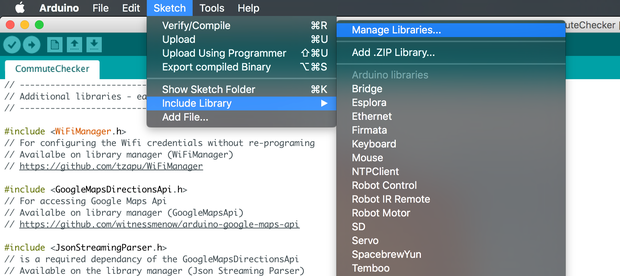
Sketch -> Include Library -> Manage Libraries
This will pop up the library manager window, in the search bar search for the following libraries and install them.
- GoogleMapsApi (A library I wrote for connecting the Google Maps API)
- WifiManager (For configuring the Wifi credentials without re-programing, I have two instructables explaing this in more detail)
- Json Streaming Parser (Required by Google Maps API library)
- ArduinoJson (Used for saving a configuration file in JSON format)
- Double Reset Detector (Used so you can press the reset button twice to enable config mode on WifiManager)
- Adafruit Neopixel (Used for controlling the Addressable RGB LEDs)
- NTPClient (For keeping the clock time used on the 7-segment display)

Arduino Library Manager
There is one library that is not on the library manager, I've asked the author to add it and they thought it was a good idea, but at time of writing this instructable it is not yet there. Search for TM1637 as above just in case it does get added, but luckily it's no big deal to add it ourselves.
- Go to the libraries' GitHub page
- Over on the right of the page there is a green Clone/Download button, click it and click "Download as Zip". Save this zip file anywhere easy to find on your computer.
- In the Arduino IDE go to:
- Sketch -> Include Library -> Add .Zip Library ...
- Navigate to the zip file you downloaded.
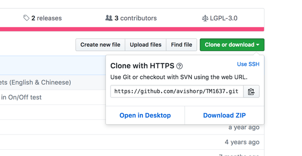
Download library directly off Github

Sketch -> Include Library -> Add .Zip Library ...
Step 3: Preparing the Mount

Ok! Now it's time to really get started!
The frame comes with a photo mount, but the hole in the center of it is too small. The first thing we need to do is to cut the mount to make the hole bigger.
We need to dismantle the frame as shown in photo one. No tools needed it all just comes apart.
- Bend the tabs at the back of the frame and remove the backing piece
- Take out the white photo mount.
- Remove the spacer piece and carefully remove the glass from the frame. We don't need the glass for this project.
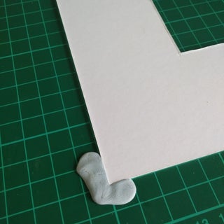
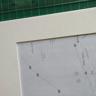
Take the white mount and place it on a surface you don't mind getting cut
I think it's a good idea to hold it in place before measuring or cutting, I'm using blu tac as shown.
We now need to mark the mount for where to cut, I used the width of my ruler as a guide (which was about 3 cm, or an inch and quarter in American money). Mark all 4 sides lightly with pencil. You should end up with a square as shown.


Carefully use your sharp knife, with the guide of your ruler, to cut the mount. Be careful where the corners of the square meet as we do not want to cut past them. My advice here is to let the knife do the work (don't lean too hard) and be careful that you are staying close to the ruler.

I was pretty happy with how mine turned out!

Step 4: Getting Your Map

Next we need the map that we are going to use for the project. There is quite a lot of text in the this step as I'm trying to be a descriptive as possible if people are not too familiar with photo editing etc. I promise it's not as long as it looks!
Go to Google Maps and zoom and position the map so all routes that you want light up are visible. Remember that you will be putting it in a square mount, so make sure they are centered and will fit in the square (We can test this later).
Take a screen shot of the map. Press the ALT + PrtScn button on your keyboard for a windows or press cmd + shift + 4 on a mac. (If you are on Linux you are on your own!)
We are now going to need to edit the photo, I like Paint.net for windows as it's free and easy to use. (I haven't found a similar one for mac, please let me know if you have a recommendation!)
Open paint.net, go to Edit -> then press Paste, this will copy the screen shot into paint.net (It will probably ask about expanding the canvas, say yes to this.)
We now need to crop out a square that will fit in the frame. Down the bottom right of paint.net you can change the values it's measuring in, change this to inches

Select "Rectangle Select" from the toolbar, press down your mouse at the top left of where you want your square to be, hold down shift (this keeps the rectangle select a square) and select a 8.5 inch square (The measurement is down beside where you changed it to inches). Remember that mount will be covering some of the photo. Once you are happy with what you have selected, select Image -> Crop to Selection.
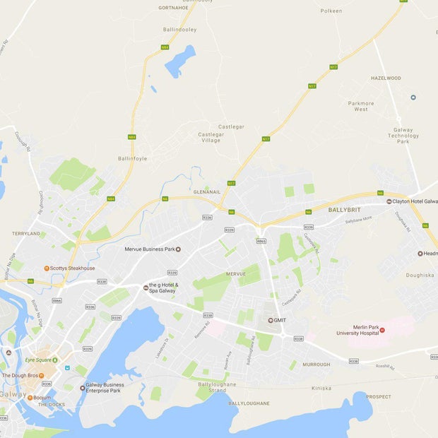
You will now have a square map area
This would be a good point to print out a black and white version of your map to see how it fits with the mount, just make sure you can see all your routes, and you dont really want the LEDs to close to the edge. If the route doesn't fit you might be best off adjusting the zoom on google maps and starting again. My first attempt had routes too close to the edge.
This effort was cutting off the start of the route
To make it easy for ourselves for placement of pages later, it's good to give ourselves guide lines that mark the center of each edge of the map. Go to Layers -> Create new layer
Select the shapes icon on the toolbar, make sure it's set to rectangle, make the brush width 1. Start holding down your mouse from outside the photo on the top left, and drag your mouse outside the photo on the right. Move your mouse down til the second measurement on the bottom bar is 4.25 (measurements are beside where you changed the measurements to inches).
Repeat the above except move your mouse to to the bottom of the photo and move right, you should end up with 4 squares as shown

Now select your rectangle select tool and start somewhere close to the top left of the photo, hold shift again and draw a square

Press delete, you will now be left with 4 lines marking the edge of each side of the map. The length of the lines don't need to be exactly the same as the mount will cover it.

The guide lines will help line up the map on the frame
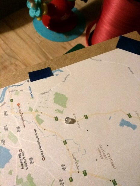
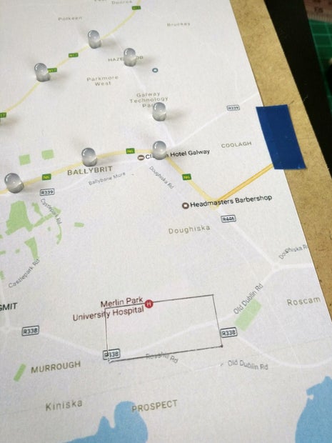
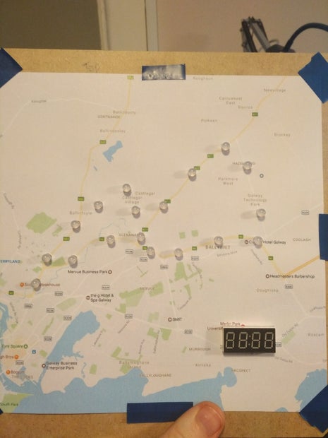
Create another new layer and add a mark for each place you want put each RGB LED along the different routes as shown in the last photo. Routes can share an LED if they take a common path (example the dot near "Scotty's Steakhouse" is used by all 3 routes). Print this out in black and white again as we will be destroying it! Double check it fits well in the mount and then print out a colour copy as well.

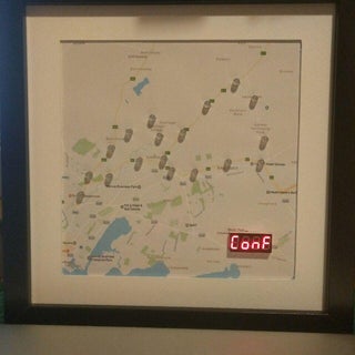
Finished product should look like this
Step 5: Let's Drill Some Holes

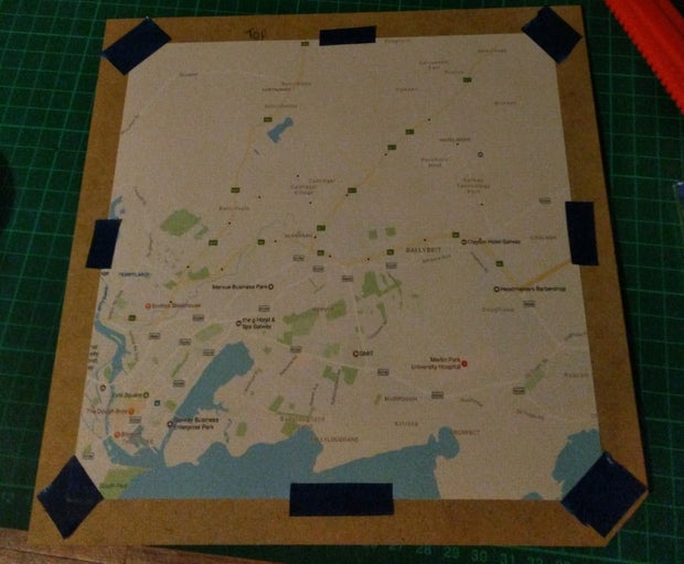
Cut the square map out from the page, it doesn't need to be cut perfectly as the mount will cover the edges. I recommend taping down the page to hold it still while you cut.

Mark the center point of each edge of the backing, line up your map using the guidelines that we added to the photo (as shown in the picture below).

Tape down the map to the backing using the PVC tape, the PVC tape works well here as its not sticky enough to tear the backing. I put the tape in the center of the page in picture below, but you would be better off not covering your guideline to make sure everything is till lining up, just put tape in the corners instead.
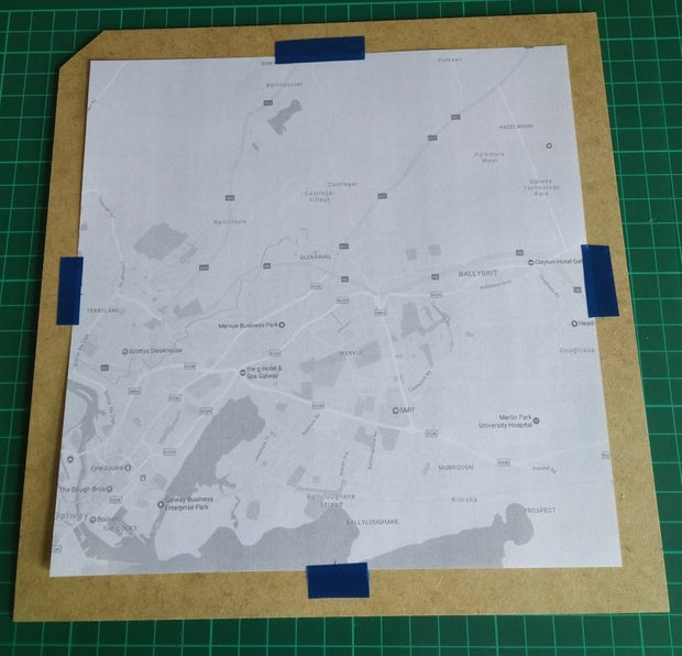
Mark the top of your backing, you don't want to end up not knowing which way is which when you are changing pages later!
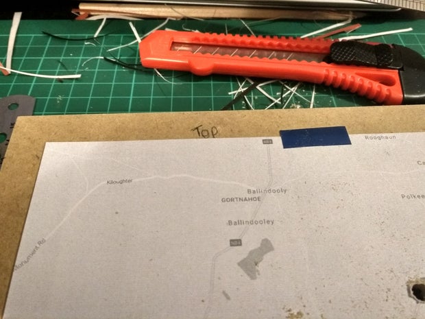
You can use the frame divider to give yourself a platform with some height to drill your holes without damaging your table, try place the hole you are drilling near the divider edge though, as the backing is a little bit too flexible when drilling in the middle.
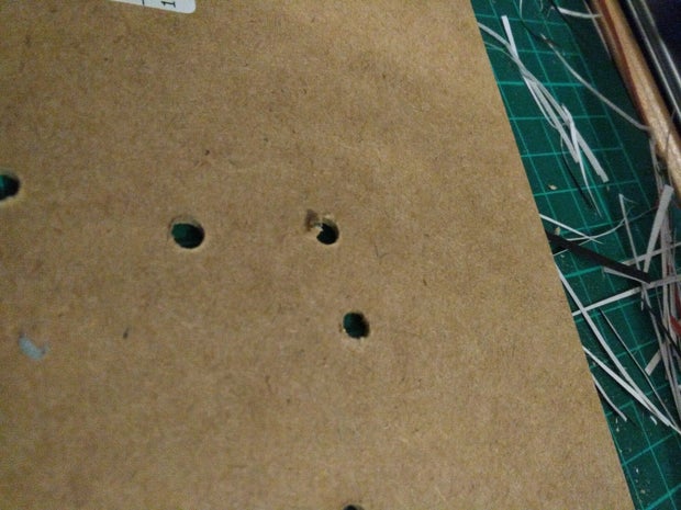
Drill holes from the front of the page for each dot.
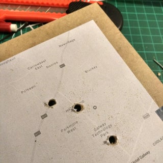

The far side of the backing might have some holes that are a little bit burst out as seen in the last picture. You could maybe minimise this by drilling the backing on top of scrap piece of timber, rather than using the divider. It's probably best to scrape or sand any bad instances of this flat, although it should not make too much difference.
Step 6: Lets Poke Some Holes

This is weirdly one of the parts of the project I struggled with the most to find a solution that would work pretty well and not require a special piece of equipment. The solution is a little strange but I think the results speak for themselves!
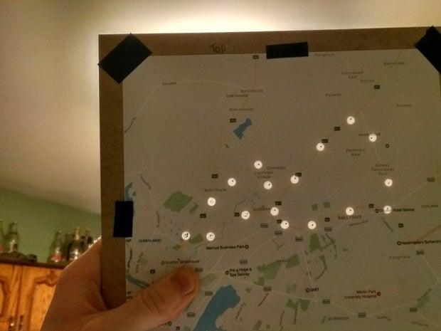
Cut out a colour version of your map and tape it to the backing using the guidelines same as before. Make sure it well taped down this time.
If you hold the backing up to the light you should be able to see all the holes behind the map, hopefully they line up with the dots on your map! Pierce a hole in map using a pencil/pen

Now take a LED, and poke it through the hole you pierced, but poke it through from the front of the map (the opposite way to the way they will end up)

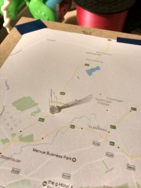
This will leave you with a surprisingly clean hole!

Then remove the LED and put it back in the hole from the opposite side. Repeat for all your LEDs
Step 7: Making Room for the 7 Segment Display

First we need to remove the headers off the 7-Segment display. Heat up the solder on the 4 pins and use pliers to remove them from the display. Adding more solder might make it easier to have all 4 solder joints liquid at the one time.

Mark on the front of the map with pencil a dot where you want the corner of the display to me and draw out the measurements of the display. You just want to draw out the measurement for the display part, not the PCB.

Carefully cut the map where your marked the rectangle, you will hopefully mark out the backing at the same time.
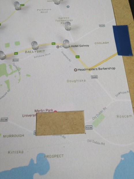

Lift the page up and continue to cut through the backing, I found pushing the knife through the whole way and cutting once it's through worked the best.

Use a file if it the display isn't fitting through the hole, or shave some of the inner part of the hole with the knife. It should fit as shown below.
Step 8: Assembling the Circuit Board (Part 1 - the ESP8266)

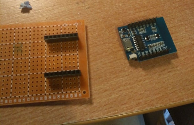
Now lets get to the circuit board. First thing we need to do is solder the male header pins to the wemos d1 mini. I like to use blu tac to hold the headers in place, make sure they are straight.


Prop up the other side with anything. Apply a small bit of solder to each pin. Repeat the same for the other side.


Now take the female header pins, and push them onto the male headers that are on the board. Put the female headers through the prototype board and solder several pins on each side to hold in place.

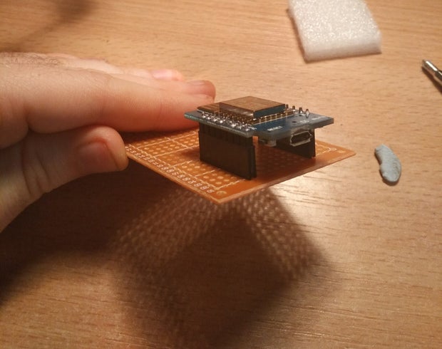
Now we have a perfectly sized socket for the board that will hold the Wemos in place, but can be easily be swapped out if needed.
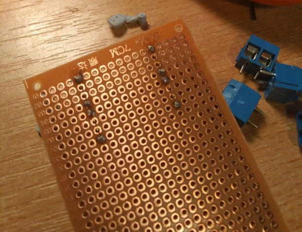
Step 9: Assembling the Circuit Board (Part 2 - the Rest of the Board, Which Isn't Much)


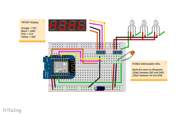
Now we need to add the rest of the circuity, we'll be basing the circuit on the circuit diagram in the first picture.
Place the screw terminals. You can hold them in place with a small bit of solder.
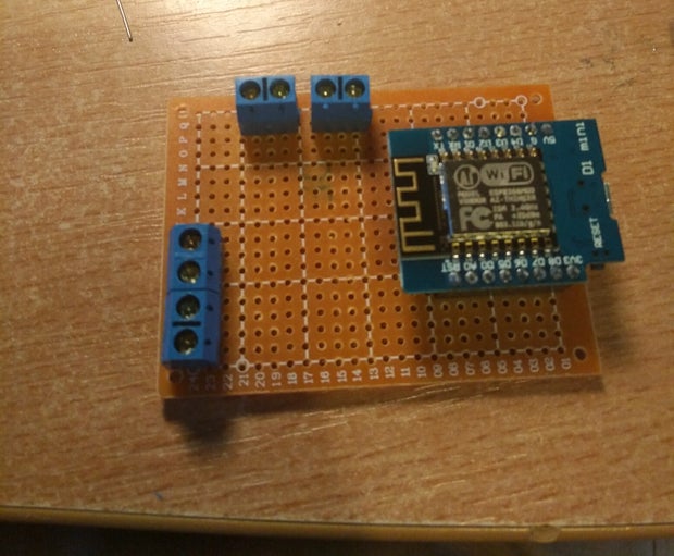
Add the capacitors to the circuit. Just bend them towards the screw terminals to hold them in place.

Add some single core wire, strip about a half inch - inch off either end. One terminal should be connected to 5v pin, one to G and one to whatever GPIO pin you want (I used D3). Solder the wire and capacitors to the screw terminals. Also solder wire to the board connectors.


Add wire for the 7-segment display screw terminals same as above. One terminal should be connected to 3.3V, one to D5 (DIO) and D6 (CLK) and then one to G (I just connected it to the other wire going to ground from the other terminal) and solder them to the screw terminals and the board connectors.


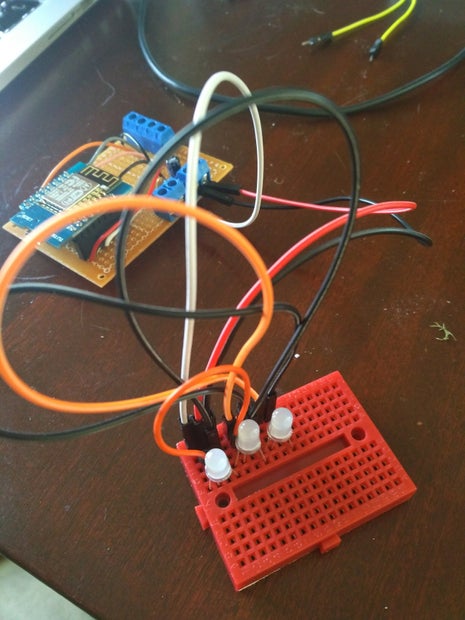
Test the board out by connecting up some PL9823 LEDs to a breadboard and running the "stripTest" from the Adafruit Neopixel library. Make sure to adjust the sketch for the number of LEDs and for the correct pin that the LEDs are connected to

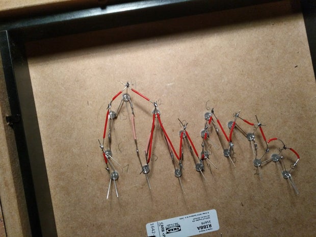
Step 10: Welcome to Solder Town

Now its time to solder the LEDs. How people have the patience for soldering LED cubes I will never understand! This wasn't too bad, but striping the wire takes a while so it isn't too fast.
A really important piece of advice I can give is to line up all the LEDs facing the same way to begin with, it will make life a whole lot easier for you. Take a look at picture one to see the pin out of the PL9823 LEDs. NOTE: If you are using different LEDs such as Neopixels, make sure you check the pin out for your LED to see is it different.

Bend D-Out of the first LED towards D-In of the second LED, and if required bed D-In back towards D-Out (it doesn't really matter where you start or in what order you go, you can adjust the order in code later).

Repeat this for all the LEDs and then solder them together, cut off any major excess. If some LED's D-Out doesn't reach the next D-In, use some wire in between.


Bend the VCC legs slightly up for all the LEDs and solder single core wire between all of them. There do not need to go in order, they just all need to make a connection to each other at some point.
Bend the GND legs downwards in a similar way and solder single core wire between all of them as well.

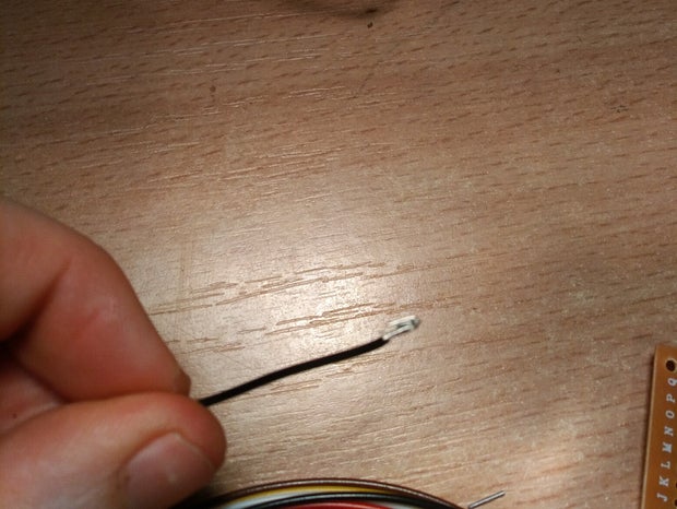
If you have it, solder stranded wire to the first LED and connect that to the terminals of your circuit board (single core will be fine, but it's just less flexible). To make a stronger connection with the screw terminals I recommend folding the wire over as shown below (blurry, sorry!).
Run the "strandTest" example from the Adafruit Neopixel library to make sure it is working as expected. Make sure to modify it for the correct pin and the appropriate number of LEDs
Solder stranded wire to the back of the 7-segment display and connect it to the screw terminals. It's a good idea to add some tape to the back for the moment to take the stress away from the connection when you are bending the wires. Run the example from the TM1637 library (making sure to update the pins).
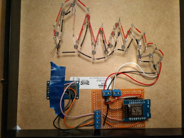
You should be in pretty good shape now!
Step 11: Gathering Some Info

We need to get some info for modifying the sketch.
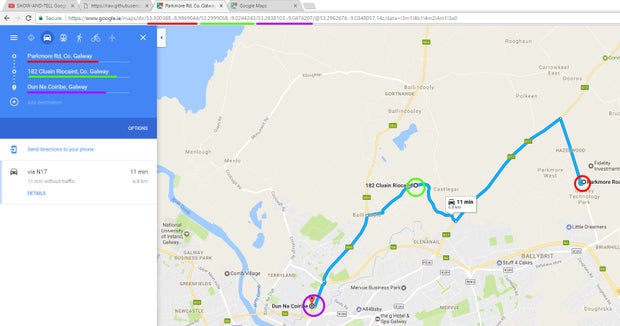
Google Map Locations:
First thing we need to get is the locations to pass to the Google Maps Api so it can return the traffic data. Go to maps.google.com and right click on where you want your journey to begin and select "Directions from here".
Then right click on where you want the journey to end and select "Directions to here"
Lastly right click on somewhere that dictates which route this is checking (even if Maps picks up the correct route by default with just a origin and destination, I suggest adding another point on the map to make sure it is checking that route). Re-order the points in the blue box in the top left so the new point is in the middle. You will now be able to take the location values from the URL in the address bar.
Note: If you need to add more waypoints to get the route you want, just add another destination by right clicking on the map and getting the value from the URL the same way as before.
Keep note of these values and repeat the steps again to get the information for all the routes you want.
Google Maps API Key:
The Google Maps API requires you to sign up for a key to use their service, It's completely free and only takes a minute.
- Go to this page
- Click "Get A Key"
- Follow the instructions to get a key
- Make sure the following URL works for you in your browser (Change the key at the end!): https://maps.googleapis.com/maps/api/directions/json?origins=Galway,+Ireland&destinations=Dublin,Ireland&departure_time=now&traffic_model=best_guess&key=PutYourNewlyGeneratedKeyHere
Keep note of this key.

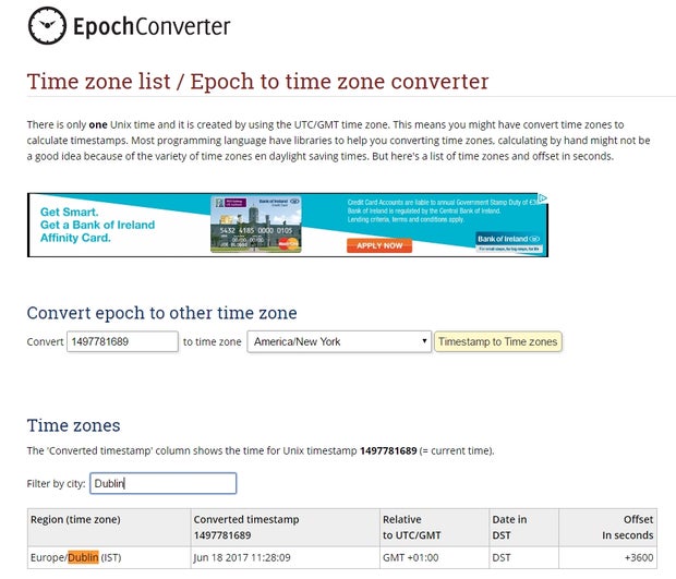
Timezone Offset:
You need to get the offset for your timezone, go to the following website and search for a city in the same timezone as you. Take note of the value in the "Offset in Seconds" column.
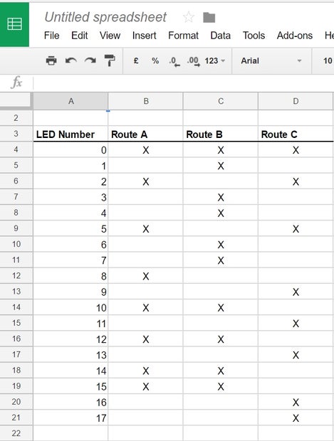
LEDs Contained in Each Route:
We need to get a list of LED addresses for all the LEDs that are contained in each route.
Start by numbering your LEDs, the first LED that is connected to the ESP8266 is address 0, the next LED that the first one is connected to is address 1 and so on, label all of them. Your last address should be one less than the amount of LEDS you have (because we started at 0)
Now each route mark which LEDs should light up when that route is active. I used a spreadsheet to mark which ones but you could just as easily use a page. As you can see LED 0 lights up for all 3 routes, LED 1 only lights up for B etc. All LEDs should be assigned to at least one route!
Step 12: Software Time (Also Known As the Moment of Truth!)

First thing you will need to do is get the sketch for this project off my Github
When you have the file in the IDE, the first thing I would do click the "Verify" button (The one that looks like a tick), just to make sure you have everything setup correctly.
-----------
Scroll down to the comment "Change the following to adapt for you" and make the following changes
- Change the pins if you used different pins than me
- NUMBER_OF_ROUTES Change the number of routes if you have a different number
- NUMBER_OF_LEDS Change the total number of LEDs
- BRIGTHNESS is how bright the LEDs are, I would leave it to something low like 16, I found this worked best, but this can be increased if needed
- timeServer No need to change the time server
- NTP_OFFSET is the offset value you got in the previous step
- MEDIUM_TRAFFIC_THRESHOLD & BAD_TRAFFIC_THRESHOLD s are the amount of time slower than the normal travel time a route should be before turning yellow or red, you might want to play with these values to see what suits you. One thing to note, the travel time in traffic is often less than normal travel time, so the threshold should probably be lower than you think.
- apiKey (optional) is where you can add the API Key from the previous step to the sketch if you want, but you can also add it through the config portal page (I'll show you this in the next step). I didn't add this to my sketch (mainly so I could share my sketch with you guys without changing it it!)
- delaybetweenApiCalls is the delay for how often it checks Google Maps for new travel times. The total amount of requests needs to be below 2500 a day, remember though that every route is it's own request.
- Say for example you had 5 routes
- That means that you can check google maps 500 times in a day
- There is 86400 seconds in a day, so if you are checking 500 times that means you can check once every 173 seconds
- Which would be delayBetweenApiCalls = 1000 * 173; (which is about every 3 mins)
- delayBetweenDisplayChange is how often the 7 segment cycles between displaying the travel time and the real time. I found every 15 seconds was pretty good but change this if you like
- Origin should be the value of the start of your journey the you got from the google maps URL in the previous step
- Destination is the value of the end of your journey the you got from the google maps URL in the previous step
- Route LEDs arrays are the list of LEDs of each route, use the table that you gathered on the previous step.
- The first LED in the array will be the last one to light up when displaying the route so put the addresses in the reverse order that you want them to light up.
- Create new arrays for additional routes, it doesn't really matter what they are called.
- In populateRoutes method there are calls to setRoute method, you should have one setRoute call for each route and they should be modified like this
- Param 1 - Id - increment this for each route
- Param 2 - Route Name - String representing the name of the route, only used for the serial monitor so not important
- Param 3 - Waypoint - the way point value for the route that was gathered in the previous step. Needs to have the "via:" before it!
- If you need multiple waypoins for one route they should each have "via:" before it and be separated by "%7C"
- e.g "via:waypoint1%7Cvia:waypoint2"
- Param 4 - LED Array - The LED array for the route defined above
- Param 5 - LED Count - Number of LEDs in Array
- Param 6 - Route Label - label for 7 segment display.
- I have up to letter F defined (ask if you are having trouble if you need more than that!)
That should be it! Upload the code and cross your fingers :)
Step 13: Finally - Configuration


The last thing we need to do is to configure the WiFi and API Key (If you didn't set it in the previous step).
We are using a library called WiFi Manager, which can host it's own access point on the ESP8266 to enable you to configure the settings (this is handy if you want to bring the device to a new network)
Note: if you are doing the configuration with your phone, send yourself the API key via email or something as your phone will lose internet connectivity while connected to the Config Portal
Plug in the device and press the reset button on your ESP8266 twice, this will force config mode. Conf should appear on the 7 segment.
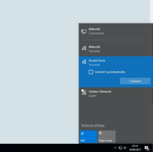
You should now see a new WiFi network appear called "RouteCheck", connect to it, the password is "thepassword" (this can be changed in the sketch if you want).
Open your browser and try go to any website, you should get redirected to the config page. Click the "Configure WiFi" Button. You can click on the WiFi network name you want to connect to and type it's password into the password box.
Add your API key into the box shown below
EDIT: Whoops, I forgot to mention once everything is working you need to hot glue everything in place! Hot glue each of the LEDs into place and also hot glue the seven segment display and prototype board to the frame too. See the photos attached to this step for example of my hot glueing (see, it doesn't need to be neat!)
That's it! Thanks for sticking with it if you are still here! Hopefully you enjoy this project and please let me know if you have any questions on any of the steps.

Second Prize in the
Internet of Things Contest 2017

Participated in the
Invention Challenge 2017

Participated in the
Travel Contest 2017


