

Introduction: Arduino Controlled Finish Line


Note: I've found some improvements since I wrote this: use an IR emitter/detector pair with a higher resistance on the detector (330K ohms instead of 56K ohms). Also, A "mini" arduino should work just fine -- the adafruit.com "Trinket" for example.
Features:
- First place displayed
- Ties displayed
- Automatic reset
- Easy operation and reading
- 20 microsecond accuracy
With some basic soldering skills and woodworking skills, you should be able to complete this build in only a few evenings.
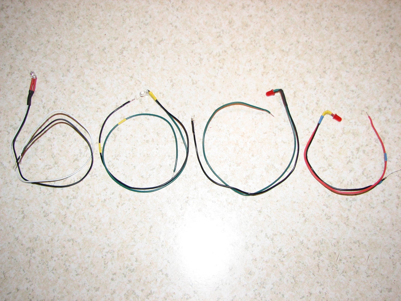
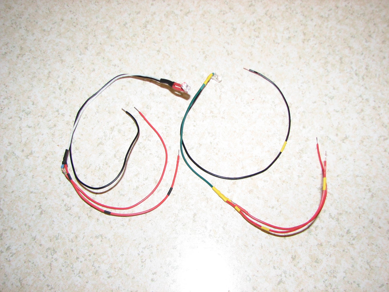
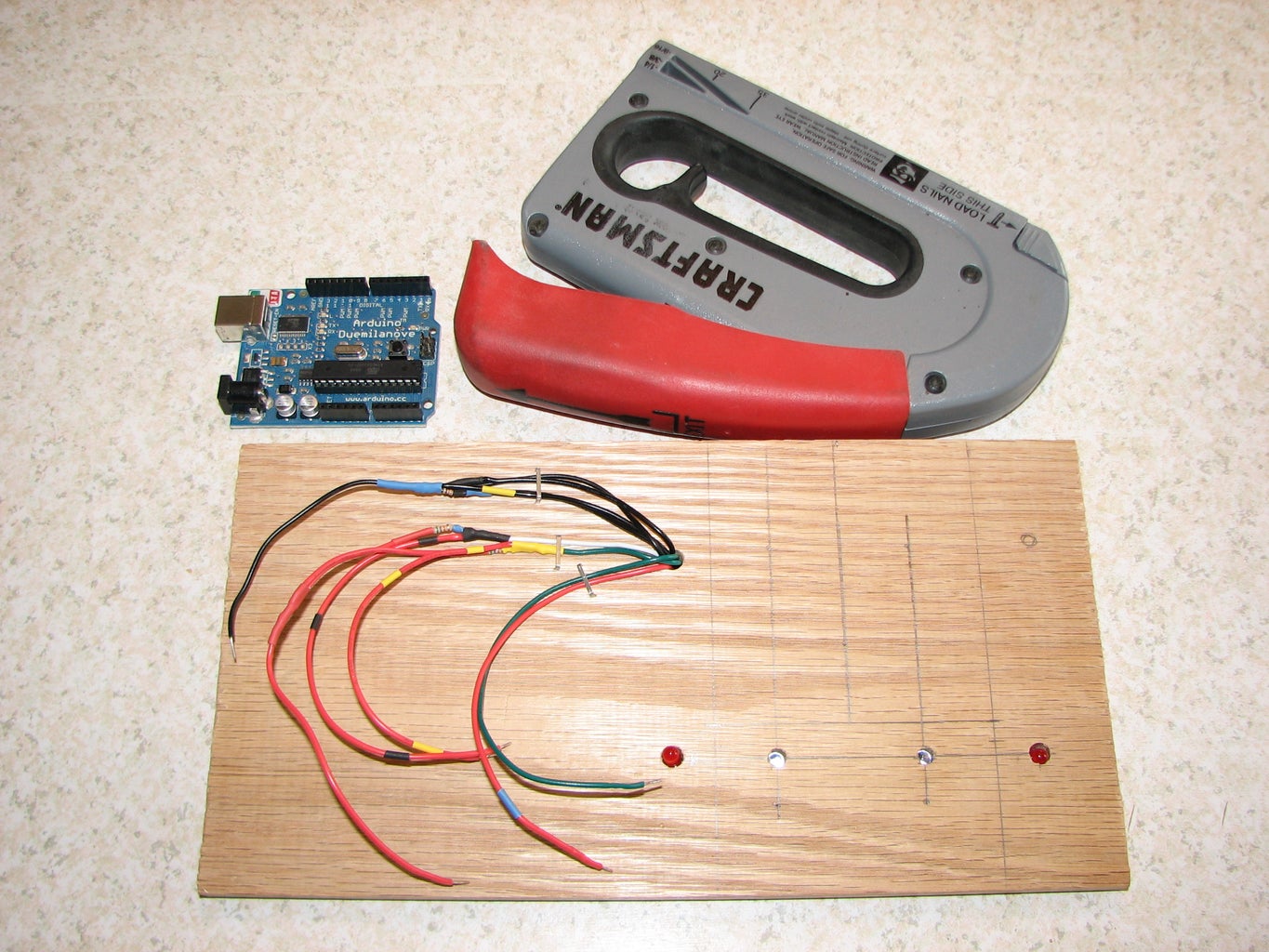
Step 1: Materials and Tools Needed
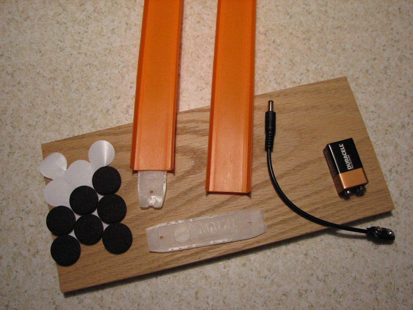
Major Components:
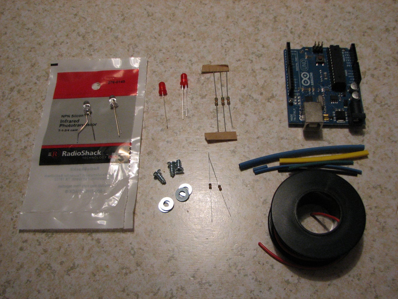
1 - Arduino (any arduino compatible) -- Adafruit .com has a very inexpensive (about $8) mini-arduino called the "Trinket" that should work just fine (I haven't tried it yet). This design should work with 5 volt or 3 volt arduinos -- in some ways, 3 volts is better (less power)
2 - 56K 330K ohm resistors (1/4 watt) [I have found that IR photosensors need higher ohm resistors (for more sensitivity)]
2 - 330 ohm resistors (1/4 watt) (or 4, if using IR emitter leds).
2 - LEDs (red, green, blue, you choose!)
2 - IR Phototransistors (Radio Shack #276-0145) or Radio Shack #276-0142: Emitter & Detector pair (the emitter can be setup on a "bridge" pointing down at the detector, to make the detector work better.) If you do use the IR emitter leds, wire them up to your battery, or input power, with a 330 ohm resister in series (like on the red leds).
1 - 9 volt battery and adapter for arduino
Additional Materials:
- Wire
- Shrink tubing
- Small wood screws - 3/8 inch long (x6)
- Small washers (x8)
- 1/2 x 6 x 10 inch board used as a base (I used oak, but could be any wood)
- Self adhesive felt feet (x4)
- Cardboard / Poster board
- Packing tape
- Hot Wheels track and track connectors
Tools:
- Soldering Iron
- Wire cutters/strippers
- Drill and drill bits
- Screw driver
- Manual Staple gun
- Scissors
- Pencil
- Tape measure
Step 2: Source Code
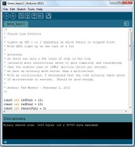
// This is the arduino sketch: Open the arduino IDE,
// create a new file and copy/paste the following code into it.
// Don't forget to upload the code to your arduino!
/*
* Finish Line Detector
*
* Lights up LED 1 or 2 depending on which sensor is tripped first
* Both LEDs light up in the case of a tie
*
* Accuracy:
* As there are only a few lines of code in the loop
* (actually more instructions after it gets compiled) and considering
* that the arduino runs at 16Mhz (million cycles per second),
* we have an accuracy much better than a millisecond.
* With an oscilloscope, I determined that the code actually takes about
* 20 microseconds to execute. Should be good enough.
*
* Author: Ted Meyers - February 2, 2011
*/
const int ledPin1 = 12;
const int ledPin2 = 13;
const int sensorPin1 = 2;
const int sensorPin2 = 3;
const int TIMEOUT = 3000; // milliseconds
// Setup runs once, at start
// Input and Output pins are set
void setup(){
pinMode(sensorPin1, INPUT);
pinMode(sensorPin2, INPUT);
pinMode(ledPin1, OUTPUT);
pinMode(ledPin2, OUTPUT);
}
// Called repeatedly
void loop() {
// Get the Sensor status
int status1 = digitalRead(sensorPin1);
int status2 = digitalRead(sensorPin2);
// Set the output LED to match the sensor
digitalWrite(ledPin1, status1);
digitalWrite(ledPin2, status2);
if (status1 == HIGH || status2 == HIGH) {
// A sensor was tripped, show the results until timeout
delay(TIMEOUT); // Wait for timeout
}
}
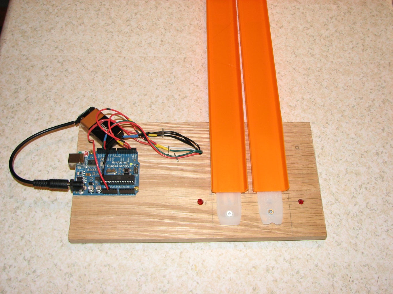
Step 3: Build the Base
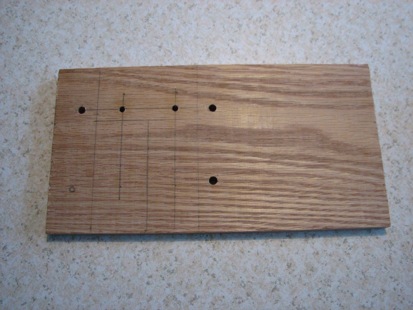
You will want to start with a board about 1/2 x 6 x 10 inches; the dimensions don't have to be exact. Cut the board to size if needed.
Make a line about 1.5 inches parallel to the long end for placing the holes for the 2 sensors and 2 LEDs. For the track I used, the sensors need to be 1.75 inches apart, mark these positions. Next mark the positions for the LEDs about 1.25 inches out from the sensors. Next draw the center lines for the two track lanes going through the sensor marks and perpendicular to the long side of the board. These lines will be used when mounting the track connector piece. While not necessary, I also marked lines to show where the track is placed.
The last hole is for the wires to go through to the bottom of the board. It's placement is not critical, just as long as it is not in the way.
Drill the holes. For the sensors, drill a 1/4 inch hole about half way though the bottom, and a 5/32 inch hole the rest of the way (this keeps the sensor from going all the way through from the bottom to the top, and also lets less light come in from the side). For the other 3 holes, drill a 1/4 inch hole all the way through (if you want, drill a larger hole for the wires, it will make it easier to push them through later on).
Step 4: Schematic
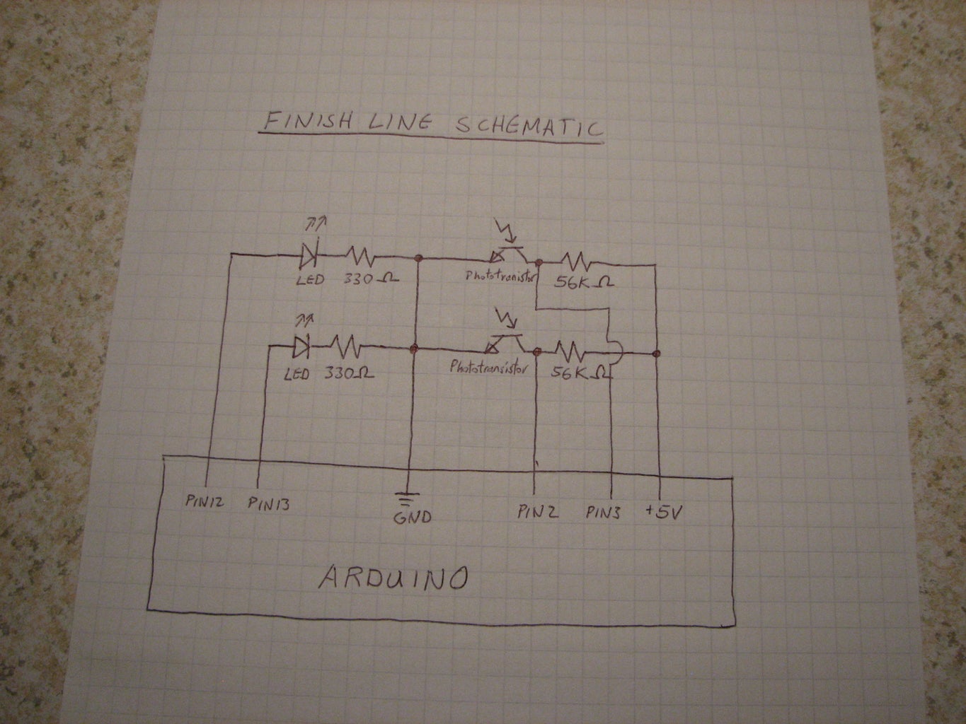
Note: I've found that a higher resistance makes the IR sensors more sensitive, I am now recommending 330K ohm resistors here.
It's a fairly simple circuit, I did not use a circuit board, just soldered the sensors/LEDs to wires along with the resistors and soldered the wires together as shown. Start by soldering long wires to the sensors and LEDs. Now solder in the resistors and the rest of the wires (power, ground, signals). Just make sure the wires are all long enough. Next place the LEDs/sensors in the mounting holes in the bottom of the base built in the previous step, and push the wires through the wiring hole to the top.
Finally, plug the wires into the appropriate pins on the arduino, and test it out. (You may have to almost completely cover the sensors to block enough light to trigger them.
Step 5: Mount Components to Base


Put the LEDs and sensors in their holes in the base (underneath). Bend the wires flat to the base and staple in place. Be careful not to put a staple through any wires. Push the wires through the hole to the topside of the base.
Turn the base over and staple the wires in place on the top.
Finally, plug the wires into the arduino and test.
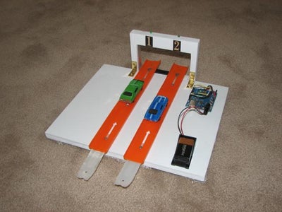
Step 6: Finishing Up


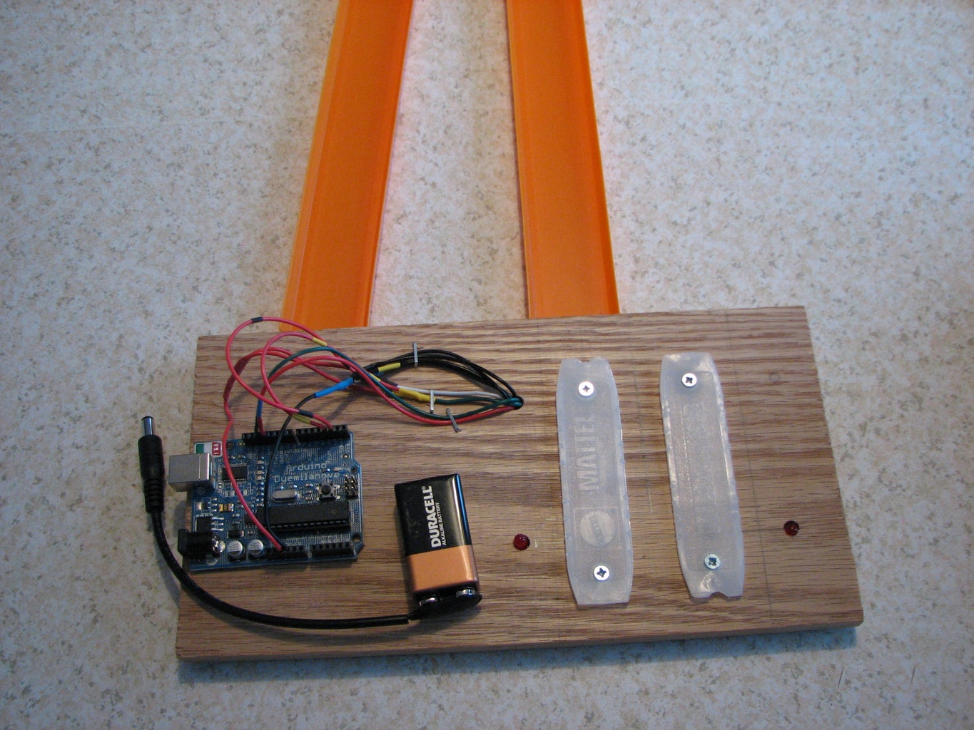
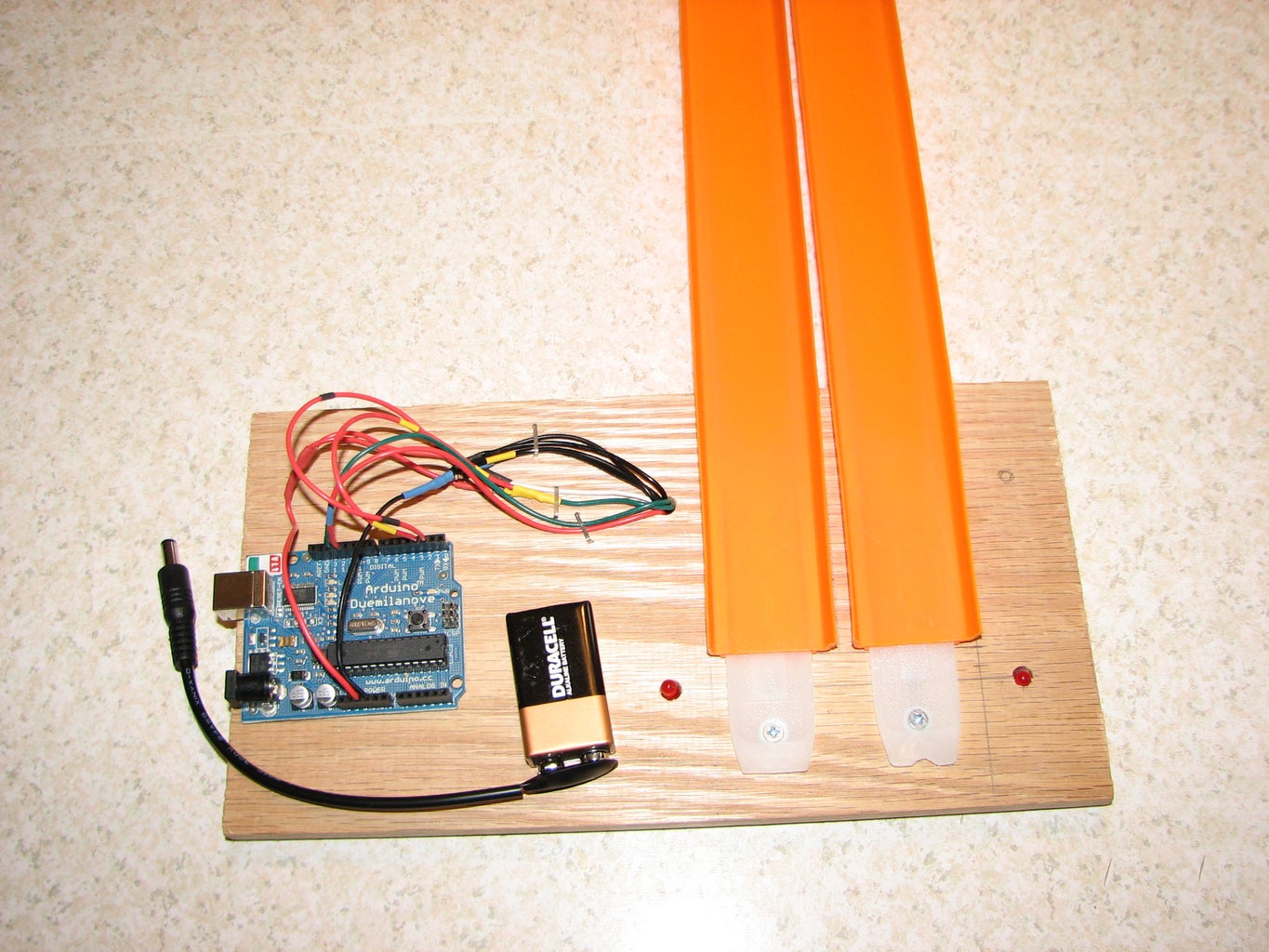
Stick on felt feet to the corners of the bottom of the base.
Cut a piece of cardboard or poster board to cover the wiring and tape it in place to bottom of base.
Turn the base right side up and use the center lines marked in step 3 to position the 2 track connectors and make marks for the screw holes using the existing holes in the connectors. Drill the holes for the screws (using a drill bit slightly smaller than the screws).
Screw the track connectors in place, putting two small washers between the base and track connector under each screw (for spacing).
Use 2 of the mounting holes in the arduino to make marks on the base for screw holes. Drill the two holes (again with a smaller drill bit than the wood screws). Finally screw the arduino to the base.
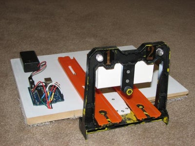
Attach some hot wheels track to the connectors on the base and you are done!
Step 7: Usage
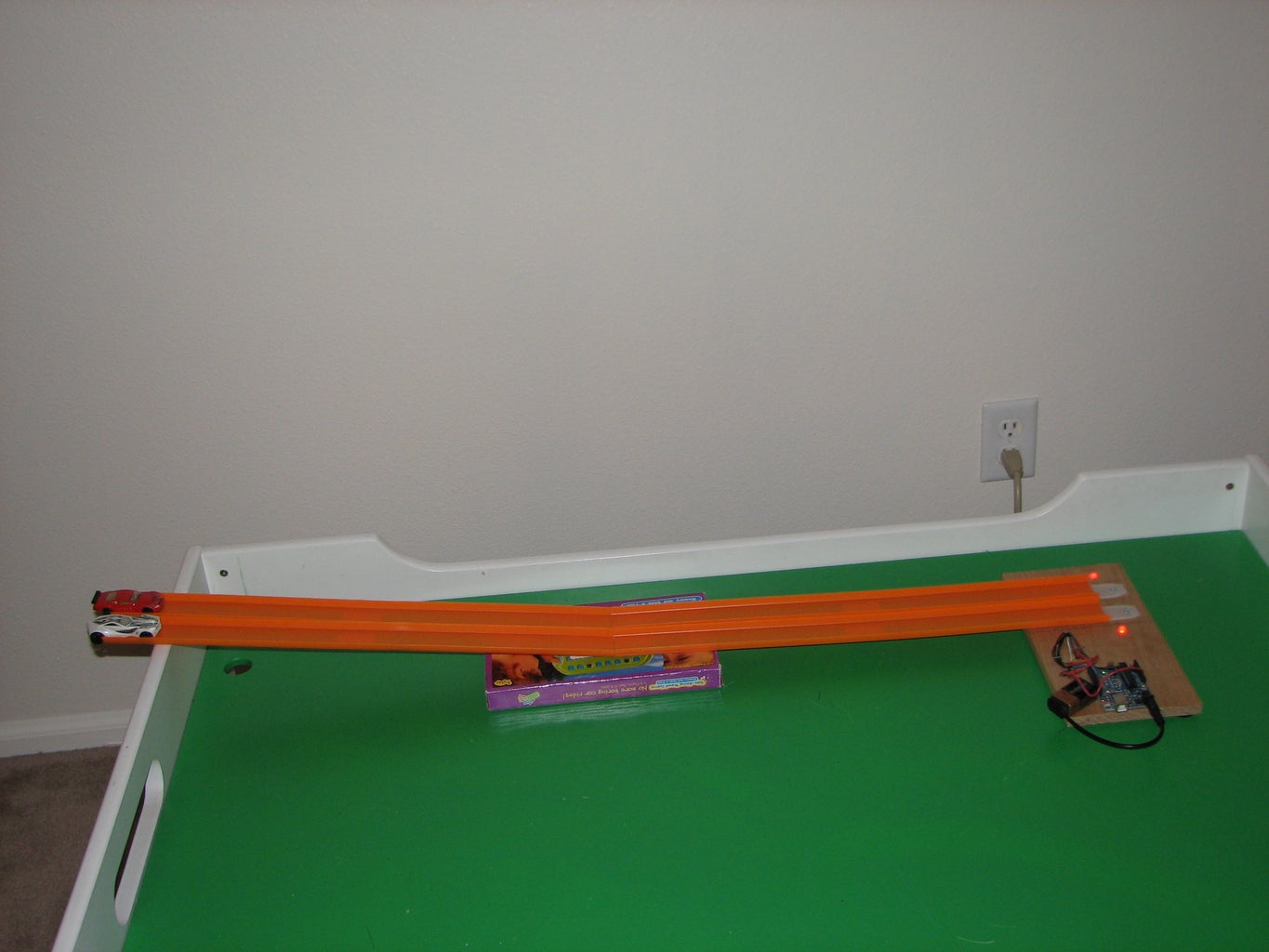
Try to set up the track so that both lanes are at an equal height and slope.
After each race, the timer will display the results for 3 seconds and then automatically reset.
When you get tired of racing, try modifying it to send the difference in time between the two lanes to the computer over the serial port. Another fun modification would be to use the two sensors to calculate the speed of one car. Good Luck!
Hope you have as much fun as we did!
Participated in the
Microcontroller Contest


