

Introduction: Arduino Cradle Rocker
Sorry, I couldn't resist the corny intense music my video editing thing suggested.
I recently had my first kid and already had a wooden cradle that my uncle (who is an awesome woodworker) made for my nephew. My nephew had long outgrown it, so I was happy to take it and avoid spending ALL THE MONEY on whatever cradle/bassinet the mommy bloggers had my wife swooning over. The cradle is a pretty simple design, basically two uprights with bolts through them that support the cradle body. There's a removable peg to lock it in place.
Within a few weeks we found that we could often quell light fussiness by rocking the cradle a little bit until our boy settled down. The night we found this out, I spent a few 10 minute stretches late at night with my arm reaching from under the covers, sleepily rocking him, happy that I'd found a way to soothe him without getting out of bed myself.
The next morning I attached a string and a little carabiner so I that I could rock the cradle without having to stretch my arm out.
The morning after that, I started brainstorming a way to just have a robot rock this kid for me. Enter the Arduino...
Supplies
Ok, this was my first Arduino project ever, so I did some experimenting and trial and error, and I'm sure there is room for improvement in my design, but here is my part list:
Arduino Uno ($13) for controlling everything
A breadboard kit ($10) for connecting wires
The stepper motor ($14) This is the most fun piece, because it's the thing that does all of the work. I started with a slightly lower torque driver, but then got this one and it's working pretty well. Feel free to get an even more powerful one.
Stepper motor drivers ($10-30) This sits between the Arduino and the motor. This specific one is apparently able to drive the motor more quietly than some others, so I went with that since the motor is going to be a few feet from my (and my son's) head while we're sleeping. I originally just bought one TMC2209 driver for ~$10, but ended up buying a pack of 4 because I had some difficulty at first and wanted to make sure I hadn't fried the board at some point. I ended up actually killing 3 boards, which brings me to my next item...
Capacitors! ($10) You really only need 1 47 uF 50V capacitor, so this box of 240 was way overkill.
A 36V power supply ($17) I originally bought a puny 12V supply, then found out that that was the source of all of my troubles and got one that was closer to the max voltage that my stepper motor could handle. If you use a different motor or stepper driver, make sure that it can handle the voltage (V) and that the Amperage (A) of the supply is at least as high as the peak Amps drawn by the motor.
Female power jack sockets ($8) This is what the power supply plugs into. You'll need to solder these to some wires to stick into your breadboard.
A big pack of jumpers ($9) so that I could put the controls wherever I wanted in the room.
Buttons ($8) for on/off, etc
A microphone amp ($11) Oh, yall didn't know this was sound activated, too?
Some small pulley wheels ($8) I ended up using these, but there might be better alternatives. More on that later.
You'll also definitely need a soldering iron and whatever you want to use to mount the motor. I personally just made a rough box out of 4 screwed together pieces of wood, and then screwed those to another piece of wood that is roughly the width of my cradle leg. For now I just have it clamped on because I don't know if I want to mar my uncle's cradle.
Step 1: Familiarize Yourself With Your Stepper Driver Pinout

The modeling program I used didn't have this exact driver board, so you'll have to reference this image. I've arranged everything in the same orientation as this image.
Step 2: Wire Arduino 5V/GND to Your Breadboard

Connect a wire from the Arduino 5V to the "+" rail on one side of your breadboard
Connect a wire from one of the Arduino GND's to the "-" rail on the same side of the breadboard
(ignore the
Step 3: Connect the +/- Rails to VIO/GND

Connect a wire from the "-" rail to GND on the bottom left of the stepper driver board.
Connect a wire from the "+" rail to VIO
Step 4: Connect DIR/STEP to Digital Pins on the Arduino

Connect the DIR and STEP pins from the stepper driver board to two of the digital pins on the Arduino. I used pins 2 & 3, respectively, but it doesn't matter as long as you set the pins in your code later on.
Step 5: Lets Go Ahead and Add That Capacitor...

I burned out 2 stepper driver boards because I didn't have a capacitor in place, so lets go ahead and add the 47uF 50V capacitor to the VM/GND pins on the driver board. Make sure the "-" pin on the capacitor is in the GND pin on the breadboard (there will be a "-" on the corresponding side of the capacitor)
Step 6: And Go Ahead and Connect That GND

On the GND that you just added the capacitor to, go ahead and connect that to the same "-" rail as the other GND.
Step 7: Connect the Motor to the Driver

Which pin goes where will depend on the motor you bought, but the one I listed has the wiring diagram on the amazon listing.
For my motor -
Connect Green & Black to M2B & M2A
Connect Red & Blue to M1A & M1B
Note: If for whatever reason your motor doesn't have a diagram, you can easily figure out which wires form a circuit if you have a multimeter. Set your multimeter to a low amp setting and have your motor disconnected. Touch one of the multimeter leads to one of the motor wires, and then try each of the other wires with the other lead. If you get a resistance reading, then those two wires form 1 circuit, and the other two form the other one.
Step 8: Connect EN, MS1, and MS2 to "-"

I'm not entirely sure that this is necessary, but I believe that it sets the motor to a smaller microstep setting on the TMC2209 driver. You can connect them to the rail "-" rail closest to them, as we'll be connecting it to the other side later on.
Step 9: Solder a Female Power Connector to Two Wires

I'm not the world's best at soldering, so you'll need to look elsewhere for that, but I did mine like so. I bent the ends of the wires so that they'd lay flat against the connector leads, then soldered the wire to the lead. I didn't have any cord heat shrink stuff so I just wrapped them prodigiously with electrical tape.
Step 10: Connect Your Newly Soldered Female Connector

Please don't plug in your actual power supply yet.
Red wire to "+", black to "-"
Step 11: Connect Those to VM/GND

Connect those "+" and "-" rails to VM and the GND next to it. The ones with the capacitor on it.
Step 12: Admire Your Handiwork

Alright, you now have the motor and driver completely set up! From here on out we'll just be doing controls. By the way, going forward:
- If you've disconnected your driver for any reason, don't try to connect it while your 36V power is plugged in. I killed my 3rd driver board like that.
- Do plug in the 36V power before plugging in the Arduino power. I didn't personally fry an Arduino, but along the way I saw many a warning about this.
Step 13: Optional - Check Your VREF
The TMC2209 has a potentiometer that controls current to the motor. If you got the same driver that I did, you can read about that here. If you want to adjust the setting:
- Disconnect all power and disconnect the motor wires from the driver.
- Disconnect the wire to the EN (enable) pin on the driver. This is the pin in the top left corner.
- Plug in your motor power supply (the 36V one)
- Using a multimeter set on 20V, touch one lead to a source of GND (I used a wire connect to my "-" rail) and touch the other lead to the VREF pin. Please don't touch the lead to anything else, you CAN short your driver if you do.
- Use a small screwdriver to gently adjust the potentiometer screw. For my board, counterclockwise = more power. My VREF personally reads ~ 0.6V.
Step 14: Buttons!

Next up, connect your buttons like so. They don't need power.
- Connect a "-" rail of your button breadboard to one of the GND's of the Arduino. You can also just chain it off of the other breadboard's "-" rail if you want.
- Connect one pin of each button to the "-" rail
- Connect another pin of each button to a digital pin on the Arduino.
I used 4 buttons:
Motor on/off
Motor continue
Microphone on
Microphone off
More on these when we get to the code, but I used distinct microphone buttons simply because I didn't have LED's to let me know if the mic was on or off, so having distinct on/off buttons made it foolproof.
Step 15: Add the Microphone Board

This one is simple, and Adafruit has good instructions (and soldering basics!) here.
- Connect "-" to a GND
- Connect GND on the mic board to "-" (you could directly connect GND to GND and skip the previous step, really)
- Connect VCC to the 3.3V power on the Arduino. This is important as this power supply is less "noisy" than the 5V, resulting in better microphone readings
- Connect OUT to an ANALOG IN pin on the Arduino. I used A0.
Step 16: This Should Be the Final Result!

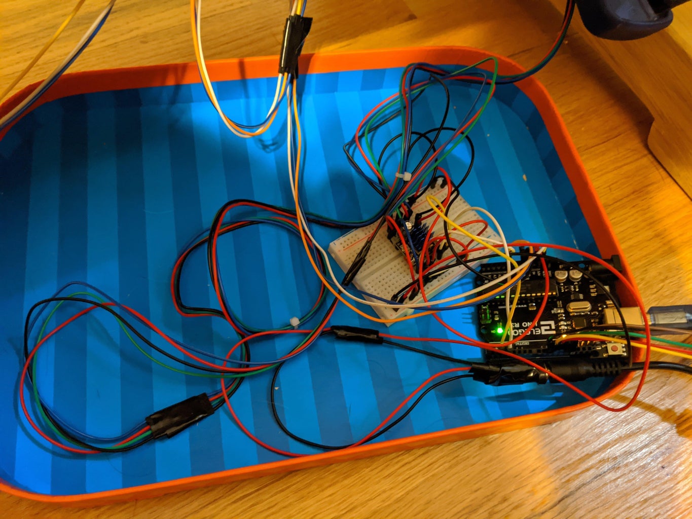
Everything should be ready now. Here's a picture of the final diagram and my jumble of wires in reality. Lets look at some code!
Step 17: Code!
Ok let's look at code! This isn't my cleanest work, but it gets the job done. I've added comments to explain everything here, but bear with me.
I used Arduino IDE for all of this (available on Windows and Mac for free)
The jist is this:
Set a motor speed and distance to turn.
Set a number of rocks (swings) to do.
Turn the set distance for 1 swing. Swing a set number of times.
In between all of that, watch for button presses or listen to the microphone to see if the motor should turn on.
You're going to need to adjust speed, distance, and mic sensitivity values.
Motor speed will affect volume and torque. The faster the motor goes, the louder it is and the less torque you get. Mine is currently almost silent, so it's possible to get it to run without making much sound.
#include <Stepper.h> // "standard" stepper motor library

//#define DEBUG 1 // uncomment this when you want to adjust microphone levels

// Button setup - these correspond to where the digital pins you connected to the buttons
const int motorEnablePin = 10;
const int continuePin = 11;
const int micDisablePin = 12;
const int micEnablePin = 13;


// Mic setup - A0 here is the analog in for the mic. Sample window is in millis
const int micPin = A0;
const int sampleWindow = 1000;
unsigned int sample;
bool micEnabled = false;
double micSensitivity = 0.53; // you'll probably need to change this
			// For me, around .5 was good enough to not fire on small cooing<br>			// but will fire for small cries<br>
int stepsPerRevolution = 3200;  // change this to fit the number of steps per revolution for your motor
				// My motor is 200 steps/revolution
				// But I set the driver to 1/16 microsteps
				// so 200*16 = 3200... honestly no idea if this is the proper way<br>				// to do this

Stepper myStepper(stepsPerRevolution, 2, 3); // 2 & 3 are the DIR & STEP pins
int stepCount = 0;

int motorSpeed = 95; // you'll need to adjust this according to your cradle & baby weight
int numSteps = 90; // The distance the motor will move.
		   // You'll need to adjust this based on the radius of the wheel you attach
		   // to your motor. This and speed will likely be trial and error.
		   // Note - higher speed on stepper motors = lower effective torque
	          // If you don't have enough torque, your motor will skip steps (not move)<br>
int oldmotorButtonValue = HIGH;

bool enabled = false; // motor enabled?
int loopStartValue = 0;

int maxRocks = 100; // how many times you want it to rock before turning off
int rockCount = 0;

void setup() {
  #ifdef DEBUG
  Serial.begin(9600); // for debug logging
  #endif

  pinMode(motorEnablePin, INPUT_PULLUP); // This is a setting for the buttons to work without power
  pinMode(continuePin, INPUT_PULLUP);
  pinMode(micEnablePin, INPUT_PULLUP);
  pinMode(micDisablePin, INPUT_PULLUP);

  myStepper.setSpeed(motorSpeed); // sets the motor speed to what you specified earlier
}

void loop() {
  int motorButtonValue = digitalRead(motorEnablePin); // digitalRead just reads button values
  int continueValue = digitalRead(continuePin);

  // This detects the motor button press and prevents it from firing more than once per click
  if (motorButtonValue == HIGH && oldmotorButtonValue == LOW) {
    enabled = !enabled;
  }

  micCheck();

 // If the motor is off, and mic is on, listen for baby crying
  if(!enabled && micEnabled) {
    if(getMicReading() >= micSensitivity) enabled = true;
  }


  if (enabled) {
    stepsPerRevolution = stepsPerRevolution * -1; //reverse direction
					          // With my setup its more effective to reverse on
					          // the first swing. You can put this after the loop
						  // if that's not the case for yours
    <br>    //spin motor the distance specified above
    for(int i = loopStartValue; i < numSteps; i++){

      //check for turn off
      int tempmotorButtonValue = digitalRead(motorEnablePin);

      if(tempmotorButtonValue != motorButtonValue) {
          rockCount = 0;

	// These next two lines "save" the motor position, so that next time you turn it on
	// it will continue traveling as if you hadn't turned it off. This prevents throwing off<br>	// your movement distances
          loopStartValue = i; // save position
          stepsPerRevolution = stepsPerRevolution * -1; // maintain direction


          oldmotorButtonValue = tempmotorButtonValue;
          break;
      }

      checkContinue(continueValue); // check if continue button was pressed
      micCheck();

      myStepper.step(stepsPerRevolution / 50); // how many steps to take per loop,
						// you may need to adjust this

      // make sure we continue full loop distance if the loop finished
      // this comes into play if you turned the motor off yourself and it "saved" the position
      if(i == numSteps - 1)
      {
        loopStartValue = 0;
      }
    }
  }

  delay(100); // pause 100 millis before doing the next rock. You'll need to adjust this.
  if (enabled) checkComplete();
  oldmotorButtonValue = motorButtonValue; // this is used for preventing double clicks
}

// This code is directly from Adafruit.
double getMicReading() {
    unsigned long startMillis = millis();

  unsigned int peakToPeak = 0;   // peak-to-peak level
  unsigned int signalMax = 0;
  unsigned int signalMin = 1024;
  while (millis() - startMillis < sampleWindow)
   {
      micCheck();
      if (digitalRead(motorEnablePin) == LOW) enabled = true;
      sample = analogRead(micPin);
      if (sample < 1024)  // toss out spurious readings
      {
         if (sample > signalMax)
         {
            signalMax = sample;  // save just the max levels
         }
         else if (sample < signalMin)
         {
            signalMin = sample;  // save just the min levels
         }
      }
   }
   peakToPeak = signalMax - signalMin;  // max - min = peak-peak amplitude
   double volts = (peakToPeak * 5.0) / 1024;  // convert to volts
   Serial.println(volts); // Use this logging to calibrate your mic sensitivity

   return volts;
}

// Just checking for mic on & off button presses
void micCheck() {
  int micEnableValue = digitalRead(micEnablePin);
  int micDisableValue = digitalRead(micDisablePin);

  if (micEnableValue == LOW) micEnabled = true;
  if (micDisableValue == LOW) micEnabled = false;
}

// I used a "continue" button to set the rock count back to 0, so that if you have
// your code set to 100 rocks and decide part way through you want it to keep going for a while,
// you can click this button so that it will do 100 more rocks. This is definitely NOT a required
// button and I rarely use it.
void checkContinue(int continueValue) {
  int continuemotorButtonValue = digitalRead(continuePin);
  if (continuemotorButtonValue != continueValue) rockCount = 0;
}

// Increment the swing/rock count. If we've reached the rock limit, turn off
void checkComplete() {
  rockCount++;
  Serial.println(rockCount);
  if (rockCount >= maxRocks) {
    enabled = false;
    rockCount = 0;

    // return to the middle position
  for(int i = loopStartValue; i < numSteps/2; i++){      myStepper.step(stepsPerRevolution * -1 / 50); // step 1/100 of a revolution:    }  }
}
Step 18: Mounting & Wheel Setup

This is still a WIP for me, because as I said I'm not sure I want to put screws into my cradle yet.
The way I rigged mine up is as follows:
- Put a clamp to act as an arm coming off the cradle so that my wheel can pull in a straight line
- Screwed together a crude box to put the motor in, and screwed that to a base plate, which I clamped to the cradle leg
- Made a custom wooden pulley wheel with a hole to fit the small stepper pulley wheel inside. I made the center hole very tight and just malleted in the stepper pulley wheel. I drilled a hole through the wheel to the middle so that I could access the screw on the metal pulley wheel to tighten it onto the stepper motor.
- Ran a string from the cradle "arm" to the wheel. I secured the string by running it through the hole I'd drilled and just taping it in place.
The better solution to the 3rd step is to just buy a larger diameter pulley wheel in the first place. Mine is a little under 3" in diameter inside the groove and works really well for my particular cradle.
My first version used an arm instead of a wheel. It didn't work nearly as well because the force wasn't being applied in a consistent direction, and it was also really susceptible to getting thrown off if the starting position wasn't correct. Using a wheel solves those issues. I also entertained using a small pulley system, but ended up not needing to because my wheel gave me enough torque.
Step 19: Final Setup

Mount the microphone close to your kid, but in a place where they aren't going to hit any wires.
Put the buttons wherever you want, as long as you have enough wires to run to the final destination. You could also just replace the buttons with a wifi setup on the arduino, but I haven't gone that deep yet.
Good luck out there!


