

Introduction: Arduino UNO / Arduino 101 DIN Rail Enclosure & Breadboard
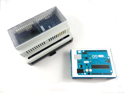


Do you want to install your Arduino / Genuino project in a control cabinet? May we can help you!
Our ArduiBox Open DIY kits are not only suitable to house an Arduino board and mount it to a DIN rail. ArduiBox comes with a breadboard and a voltage regulator for 12V DC (Vin Arduino). Along the edges of the proto area, all the IO and power pins are connected and marked. Furthermore you can stick an Arduino shield to the main board. You can connect your work via terminals with the world ouside the enclosure. Here are the main features of our enclosure kit:
- milled cab rail enclosure for EN50022 DIN rails
- prototyping plate - fits perfectely in the enclosure
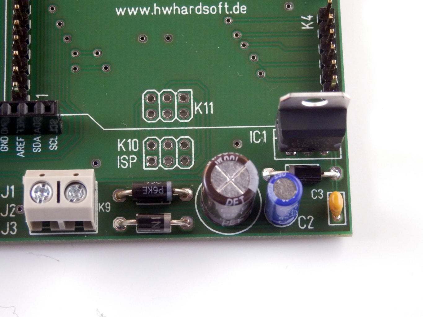
- all Arduino pins are connected to marked pins beside the breadboard
- 4x 2-pin terminal blocks
- 2x 3-pin terminal blocks
- male headers for the Arduino Uno, 101 and zero
- female headers for an optional shield (directely connected to the Arduino)
- pcb contains a layout for a 12V/1A voltage regulator
- optional reset button
Note: This enclosure is also suitable for the new Arduino 101 / Genuino 101.
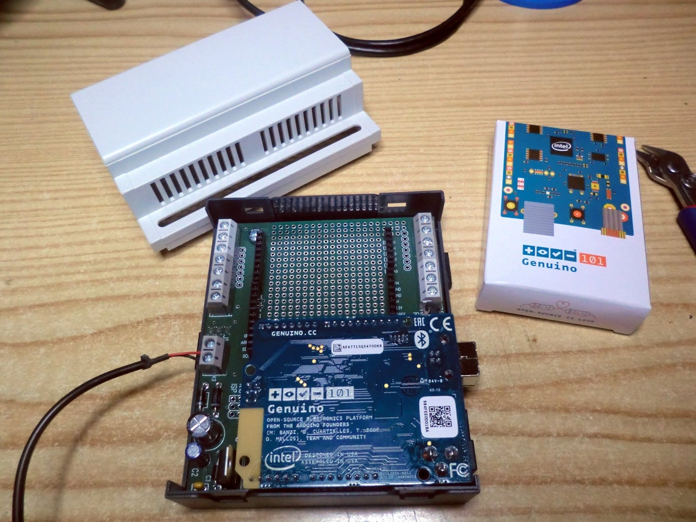
Step 1: Tools and Materials
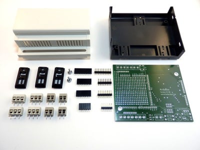
Check that you have all the parts in the ArduiBox DIY kit - the PCB, 4 female headers, 4 male headers, two 3-pin terminal blocks, four 2-pin terminal blocks, 2 self-taping screws, the milled enclosure.
You will also need the following tools:
- soldering iron
- solder
- wet sponge to clean the tip
- diagonal cutter for wires
- screwdriver for recessed head screws
Step 2: Assemble the Terminal Blocks


Find the terminal blocks, they're grey and come in 3-pin and 2-pin shapes. We'll need to slide two 2-pin and one 3-pin blocks together for the next step where we put the blocks into the proto plate. Make sure you place them so that the open ends are facing out as shown.
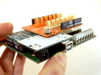
Step 3: Assemble the Male Headers for Arduino


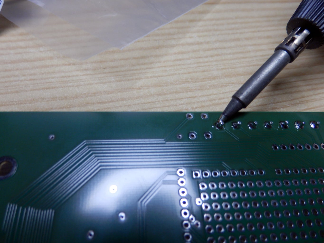
Find the 4 male headers and plug them into the female headers of the Arduino. Now you can plug the Arduino to the pcb and solder the headers.
If you don't have an optional shield its time now to realise your own idea in the breakout areas!
Step 4: Assemble the Headers for a Shield (optional)

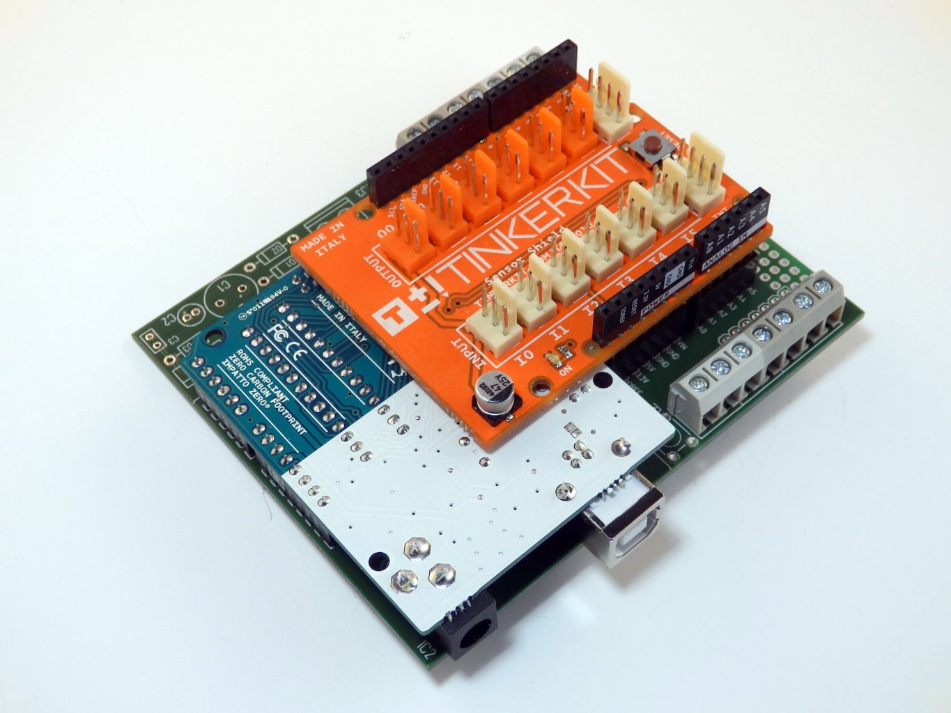


Find the 4 female headers and plug them into the male headers of the optional Arsuino shield. Now you can plug the shield to the pcb and solder the headers.
If you shield needs connections to the world outside the enclosure, feel free to solder some wires beside the terminals and connect them with the shield.
Step 5: Mount the Pcb
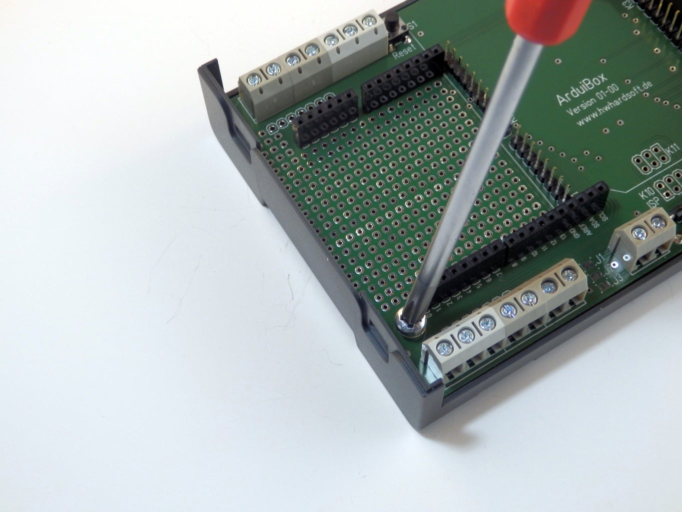
Use the two self-tapping screws to mount the pcb into the bottom shell of the enclosure.
Step 6: Mount the Din Rail Holders

Find the 3 din rail holders and plug them into the bottom shell.
Step 7: Mount Arduino and Optional Shield


Place the Arduino and the optional shield to the pcb again. Now you can mount the top shell.
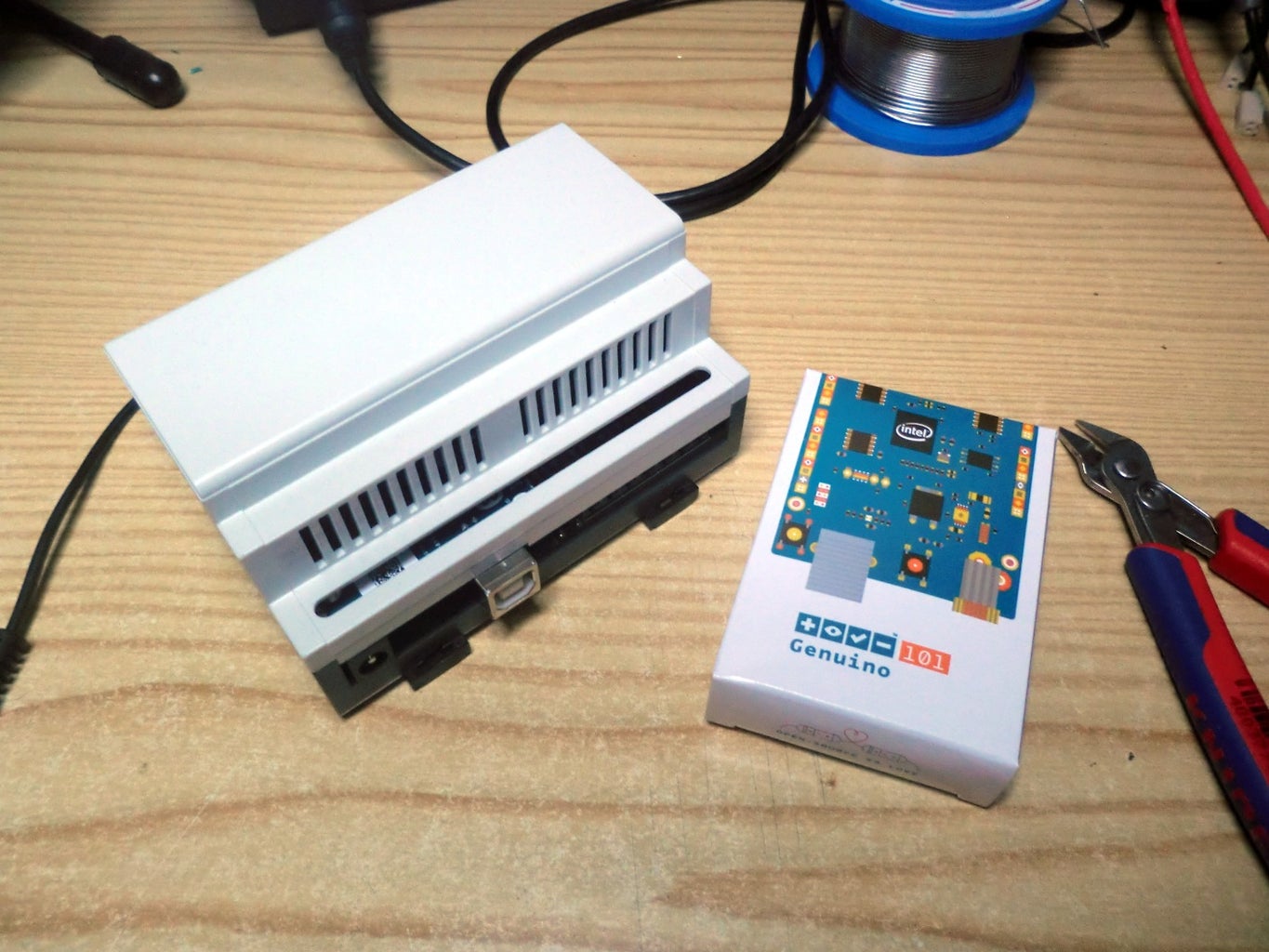
Step 8: Install It!


Put your ArduiBox into a control cabinet
Step 9: Optional Voltage Regulator

The Arduino can only handle input voltages from 9 to 12 VDC. In a control cabinet we have usually a control voltage of 24V DC. We offer an optional voltage regulator set for Arduibox which enables the Arduibox for input voltages of 15 to 30VDC

Participated in the
Tech Contest


