

Introduction: Arduino Data Logger With 2 DS18B20 and Sample Rate Control


Hi. This tutorial is for those who want to get data from their sensors with controlled sample rate or want to know more about the data logger shield or DS18B20 temperature sensor . We´ll use the data logger shield (RTC and SD) and 2 temperature sensors DS18B20 (water proof or TO 92).
In a previous tutorial i explain how to use the data logger shield (with the adafruit guide) and how to control the sample rate with the RTC. Maybe you want to visit:
Arduino Data Logger Shield. How to Control Sample Rate With Rtc
https://www.instructables.com/id/Arduino-Data-Logge...
I have translated this tutorial to share it with you, so excuse my english.
Summary of the steps
1.-Materials. All that you need for this tutorial.
2.- Address of your sensors. We will use the utility 1 wire address finder.
3.-Testing the sensors. We will use a code to show the temperature in the serial monitor and test the sensors.
4.- Sample rate control. Using the RTC we will control the sample rate and then show the data in the serial monitor.
5.- Data logger. We´ll use the entire shield to log data on the sd card.
Step 1: Materials


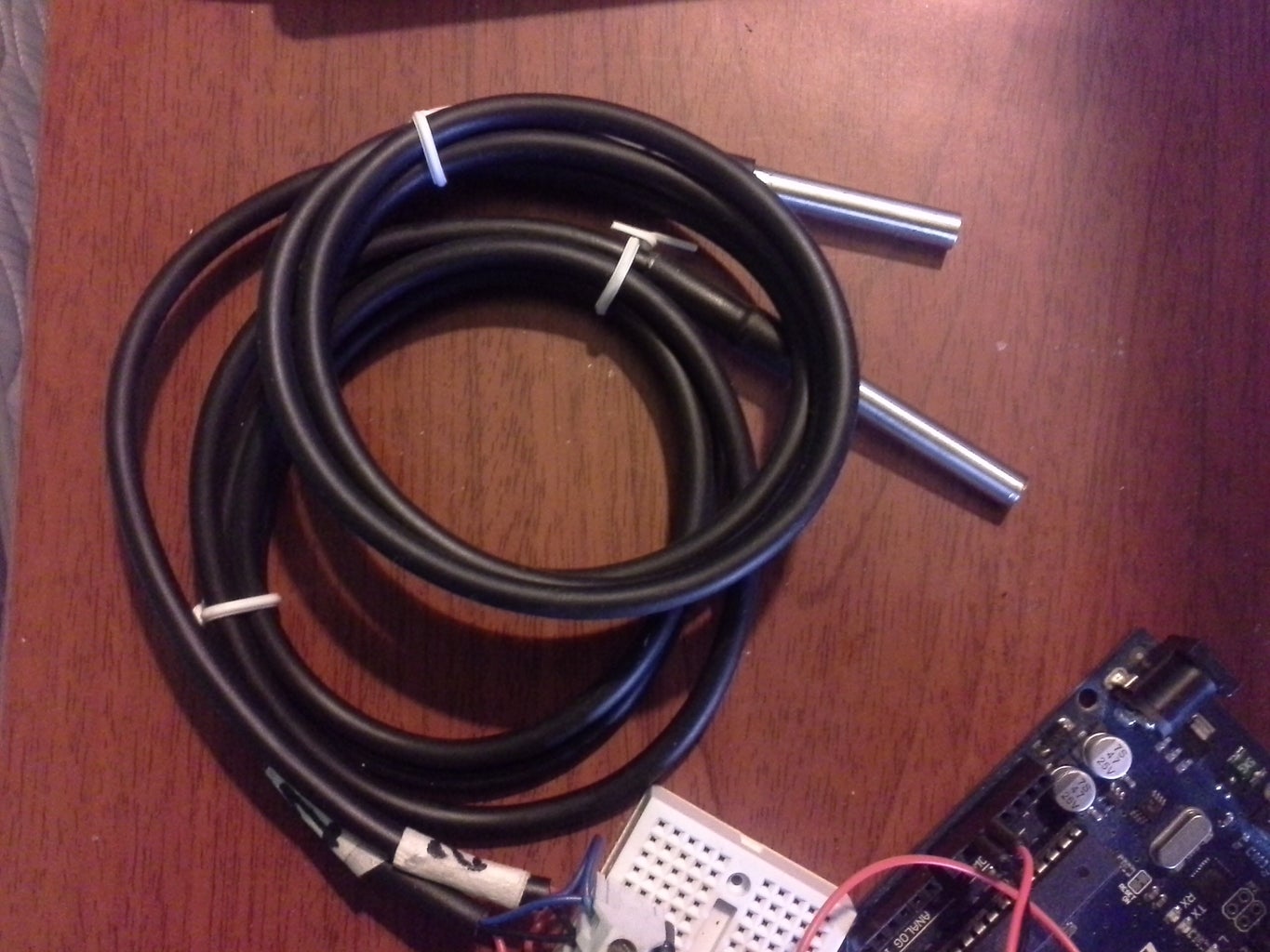
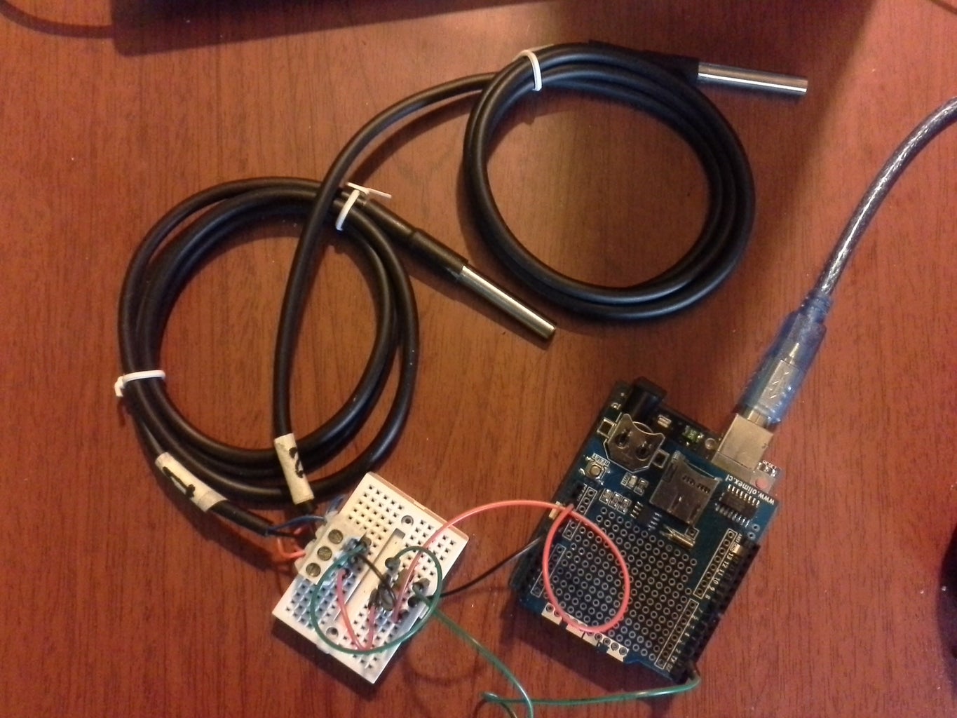
1.- Arduino UNO
2.-Data logger shield
3.- 2 Temperature sensors DS18B20
4.- One wire address finder utility.
5.- Bread board, connectors, etc.
6.-SD or micro SD card
7.-CR 1220 batery (if not included)
8.- Dallas Temperature library
9.- Onewire Library

Step 2: Address of Your Sensors

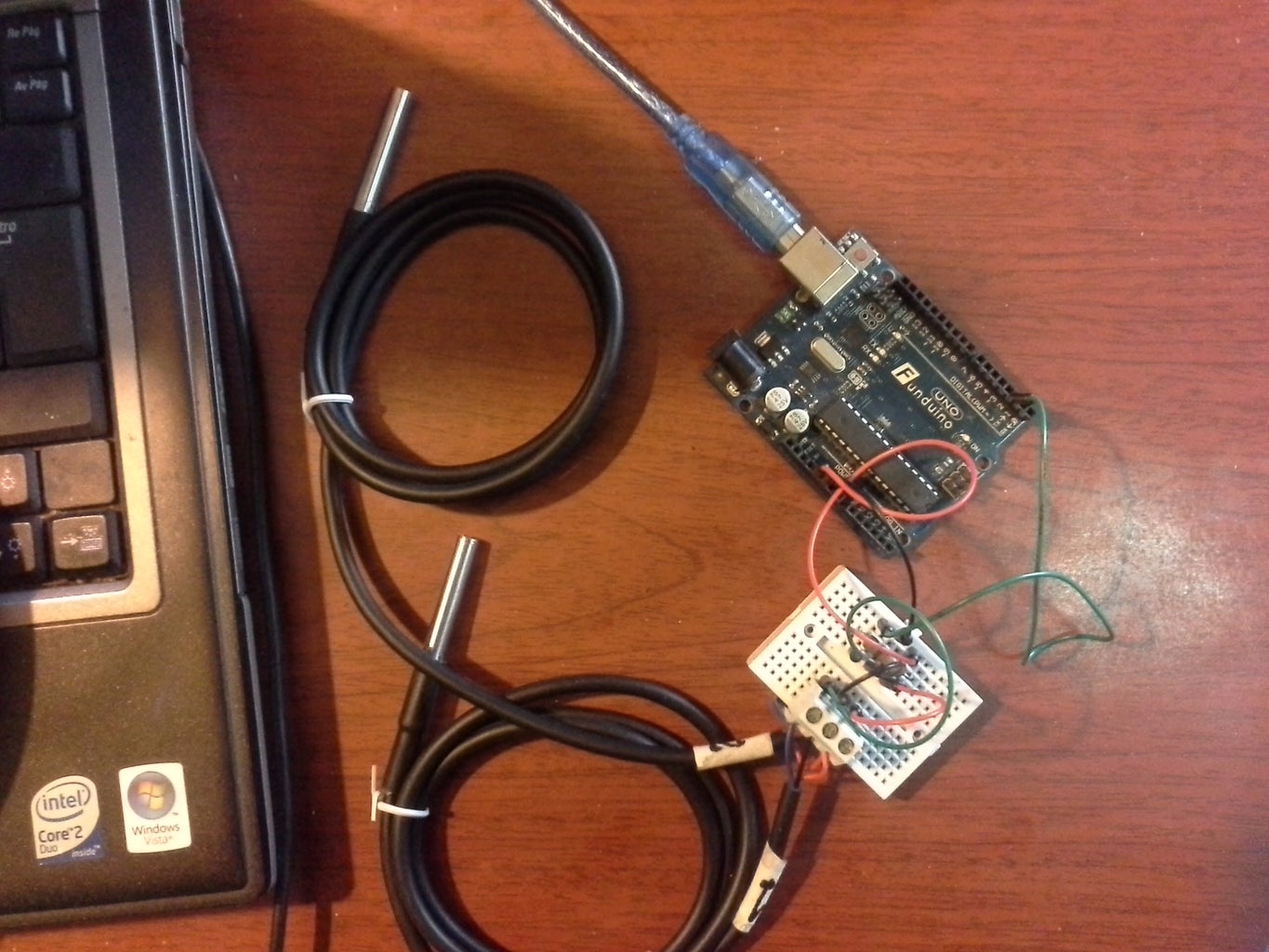
Download the utility 1 wire address finder and connect your sensor. You have to do it one by one. I´m using the normal power mode and the data to pin 3 of the arduino in this example.
My pins
Red= Vcc +5v
Blue= Data
Black= GND
There is a lot of information about this sensor in this page.
Unzip 1 wire address finder an put the file in the folder where you save your sketch. In my case windows7:
My documents---Arduino
Then open from the arduino IDE and run it
Open----My documents-----Arduino---one wire adress finder.pde
You have to copy your addresses. We wil need it in the next step.
Make sure you have instaled the libraries needed (Onewire and dallas temperature)
Step 3: Testing the Sensors


Now you can connect the two sensors. This time to pin 2 or you can change it here:
#define ONE_WIRE_BUS_PIN 2 // The pin that we are using
Every sensor has it own address. You must put your addresses here:
DeviceAddress Probe01 = { 0x28, 0xFF, 0x56, 0xC4, 0x01, 0x15, 0x02, 0x72 }; //inox2
DeviceAddress Probe02 = { 0x28, 0xFF, 0xC2, 0xD1, 0x02, 0x15, 0x03, 0xD9 }; //Inox1
Change your resolution here:
// set the resolution to 9 bit (Can be 9 to 12 bits .. lower is faster)
sensors.setResolution(Probe01, 9);
sensors.setResolution(Probe02, 9);
If everything works fine, you will have the data in the serial monitor (see the pictures)
Attachments
Step 4: Sample Rate Control


I assume that you know how to use the data logger shield. If not , please visit my previous instructable.(Link in the intro)
Now we have to use the RTC of the data logger shield. Mount it and connect your sensors to the pin 2 of your arduino(Data).
Make sure you have the libraries needed:Wire, OneWire, RTClib, DallasTemperature
The trick is to use the RTC to compare the time with the function "if".
So we have:
DateTime now = RTC.now(); // Clock call
//-------------Once we have called the clock ,we compare min and sec and print---------
if(now.second()==00){ //Sample every minute
If the second is 0 we have a "new" minute and print what we want. More details in my previous instructable (Link in the intro)
Here the examples for the serial monitor: every minute and every 10 minutes. You can see the results in the pictures.
Step 5: Data Logger


We tested the sampling rate, now we use the sd card of the shield to log data. You have to use the same connections from the previous step.
Warnings
-Some shields need pin 10 of the arduino as an output, even if it´s working (logging) . I did not.
//pinMode(10 , OUTPUT);//For some data logger shields.Uncomment if you need.
-Remenber to change your CS (chipSelect). Mine is the 8
const int chipSelect = 8; //CS pin of your data logger shield.Maybe not yours!!
-Make sure you have a tested/formated sd card compatible with your datalogger shield.
To make things easier, you can use the function "getTempCByIndex"(Celsius) or getTempFByIndex(fahrenheit), Where (0) is the first sensor and (1) the second , and so on. You don´t need the address , but you have to recognize your sensors "by hand".This example is useful if you want only one sensor, so you will have to use the index 0. See the examples.
To continue with the "by Address code" , I show you 3 examples :every 1, 10 and 30 min . I think these examples cover your needs.If you want every hour:
if(now.minute()==00 && now.second==00)
{
Print what you want
}
You can use other sensors with this structure, to have a controled sample rate.
If you want to learn more, this work is based on the following books/guides:
-Arduino Cookbook, Michael Margolis
-Exploring Arduino tools and techniques for engineering wizardry, Jeremy Blum
-Adafruit data logger shield guide
https://cdn-learn.adafruit.com/downloads/pdf/adaf...
-Progamming Arduino next steps , Simon Monk.
- Beginning Arduino, Michael McRoberts
-Arduino Temperature Control Library, Miles Burton
https://github.com/milesburton/Arduino-Temperature...
I hope this tutorial is useful for you!
Attachments
 _2_ds18b20_sample_control_sd_every_minute_by_address.ino
- _2_ds18b20_sample_control_sd_every_10_min_by_address.ino
- _2_ds18b20_sample_control_sd_every_30_min_by_address.ino
- _1_ds18b20_sample_control_every_minute_by_index.ino
- _2_ds18b20_sample_control_every_10_min_by_index.ino
- _2_ds18b20_sample_control_sd_every_minute_by_index.ino


