

Introduction: Arduino Electrometer/Capacitive Object Sensor


My passion as a maker is for robots. I have made a dozen or so, mostly using Arduino. The thing is, I'm kind of bored by most of the robots that get made-line followers, sumo, photophobes/vores, BEAM, etc. What interests me is a robot that hasn't been done to death, one with a new design, method or structure. To that end, I started thinking about sensors that haven't been traditionally applied to robots.
Most object avoidance is done with one of two methods:sonic or visible/near visible spectrum EM sensing. Infrared and "Ping" sensors each are well documented for use with the Arduino, so I've been experimenting with static electricity as an object avoidance method. Nearly every object in an environment that a table-top robot would come into contact with has a detectable static field reaching a few inches into space around it. With an array of sensitive enough detectors (and enough shielding or programming regulation to keep from detecting its own fields) a robot should be able to avoid most objects. (Of course if you're mean to your robot and line its environment with the little bags and foam from your IC collection, it won't work, but you'd be being a jerk if you did that...)
In any case, the purpose of this tutorial is just to show how an "Electrometer" works and can be made from an Arduino.
Step 1: Electrometer Basics

An electrometer is just a device which detects and/or measures an electric charge or potential difference stored in a "dielectric," which is a fancy way of saying "something that can't conduct electricity but that can have an electric charge." You may remember a Gold-leaf electroscope demonstration from science class where a piece of gold foil in a jar was folded over a length of wire, the other end of which protruded from the top of the jar. When you touched a comb that you'd just run through your hair to the wire, the foil "wings" either sucked together or shot apart, depending on how the charges and wings were arranged initially. Usually, a Van De Graff generator was the next thing they brought out, but we're not going to build one of those. Not in this particular instructable anyway...
Step 2: Parts

Materials are pretty simple.
Electronics:
-Arduino board (any one should work, but I'm using the UNO.)
-2N3819 JFET (Junction Field Effect Transistor)
-100KΩ Potentiometer
-1MΩ resistor
-Breadboard and hookup wires
-antenna (optional)
Other materials (optional):
-Balloon
-Comb
-Hair
-Soft Dog or Cat
-Roll of packing tape
-natural fiber socks
-glow-in-the-dark analog clock or glow-in-the-dark stickers
-ESD Protection Bag (should have come around your Arduino board.)
This instructable assumes that you're already familiar with Arduino-we're not going to step you through the basics of the IDE. If you have never used your Arduino before, go to Arduino.cc and at least get familiar with the "Blink" and "AnalogReadSerial" demonstration sketches.
In addition, we're going to use Processing to generate a visual "oscilloscope-like" representation of the information that the Arduino gathers and renders to the serial port. If you don't have Processing already, go to https://processing.org/download/ and choose the version appropriate to your OS for download. (Consider making a donation while you're there. It's a neat program for freeware!)
If you are familiar with one of these environments but not the other (or for that matter the Energia IDE used with the Stellaris Launchpads) then the environment you haven't used should look awefully familiar. Arduino and Energia are based on Processing. They each have different default background colors though...
Step 3: Build
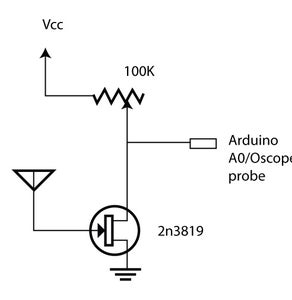
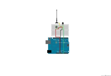
Hook everything up as indicated in the Fritzed diagram. The antenna can just be another wire-the important thing is that it be covered with insulator for most of its run, but not at the ends (one end obviously has to connect to the gate of the JFET, the other has to be exposed to sense the fields.) Also included is a schematic diagram of the circuit. (Astute makers will note it's similarity to the classic Forrest M. Mims III electrometer circuit in "Getting Started in Electronics.")
The schematic does not reflect the 1MΩ resistor between the antenna and the JFET. It is not completely necessary for the function of the circuit though-it just protects the JFET to an extent. Experiments with it in the circuit and without should have nearly identical results.
(As the schematic diagram notes, you don't have to use an Arduino if you have an Oscilloscope handy-just hook the probe up to the JFET Drain and ground it with about 5v to power, but if you do have the oscilloscope then chances are this instructable is way below your level, and the point of it is to use the Arduino anyway!)
Step 4: Program It...
Download the file Electrometer.zip (attached) and unzip it. Inside there are two files you'll want to deal with. The first is PortGraph_Electrometer_.ino, which is for the Arduino IDE. You can actually just use this if you don't mind trying to read values flying by at the speed of light on your serial monitor, but that's not very visually interesting. Launch the Arduino IDE and load this into your Arduino board.
The second file is PortGraph.pde, which is for the Processing environment. Open this file in Processing with the Arduino IDE still running and the board still connected. Run the program once, and a new output window should draw, but don't worry about it yet-just close it. What we're interested in is the debug window at the bottom. You should see a list of all the ports open on your machine enumerated like this:
[0] "/dev/tty.modem"
[1] "/dev/cu.modem"
[2] "/dev/tty.usbmodem4b461" and so on...
Switch back to the Arduino environment and under "Tools>Serial Port" see which port has the check next to it*. Then switch back to the Processing environment and look for the line:
myPort = new Serial(this, Serial.list()[3], 9600);//mine is[3]"/dev/cu.usbmodem4b461"
and replace the bold 3 with the port number in the debug window that corresponds to the port that your Arduino board is on. Save the changes and run the Processing program again (click "Play" or choose "Sketch>Run" from the Menu bar.)
*This is assuming your Arduino sketch uploaded correctly. If it didn't, figure out which port you should be using with standard web resources. It's beyond the scope of this tutorial to teach the basics of Arduino though.
Attachments

Step 5: Run It...


At this point, you should see something like what appears in the images below on screen. I have the serial window open in the Arduino IDE in the background and the Java Applet that Processing generates in the forground. If the values in the serial window are too high (say consistently above 150) or the Graph looks significantly more purple than in the image below, adjust the potentiometer down so that the circuit isn't picking up as much ambient "noise."
Step 6: DO SCIENCE!
This is the fun part!
Experiment with static charges. Use the comb in your hair (or your dog's fur) to charge it up, then bring it near to the antenna or exposed wire. You should see a spike in the Graph and serial values window (as in the image below) as it comes closer. (You might be surprised at how far away it can detect the charge!) Try the same with your balloon, or with a small piece of cellophane. Shuffle across the floor in your socks and bring your finger close to the antenna. Pull a length of packing tape off the roll within a few feet and then inches of the antenna and see what happens. If you have access to a VanDeGraff generator or other electrical discharge apparatus play with it! You may even get a reaction from a glow-in-the-dark sticker or clock hand. This is a fairly sensitive circuit!
Once you've played with (or demonstrated to a class) the various ways that you can generate a static charge, try putting the ESD protection bag over the antenna and repeating the results. Most of the time, you'll gain confidence in the safety of the shipping materials they use because there won't be a big reaction in the graph anymore. If there is, you may want to reconsider your suppliers...
In any case, I probably won't do an instructable about turning this into a robot sensor. However, I shouldn't have to:if you have built a robot before, it should be pretty obvious how this would work in that context. (The best I can give you would be the code I use if I list it as a project at letsmakerobots.com.) It's all theoretical now, but if it works it will be the first version of it that I've seen!

Participated in the
Kit Contest

Participated in the
Arduino Contest


