

Introduction: Arduino I2C Sniffer


I2C is a serial protocol used to communicate a microcontroller with external peripherals attached to the same circuit. Each peripheral must have a unique ID number called address that is used to identify it as the intended recipient of a given message. Those addresses are assigned by the device manufacturer and most of the times can not be changed. A sniffer scans all the possible addresses looking for connected devices and reports the ones it finds. This helps identify unmarked chips as then the address can tehn be googled for more information regarding the chip.
This device mimics on an Arduino UNO the behavior of the Raspberry Pi i2cdetect script, sniffing all the possible i2c addresses looking for connected devices and printing the results nicely on a 16x02 LCD screen.
To fit everything on the screen, both the high and low parts of the address are printed above the results, the high part being on a bold typeface. Two push buttons allow to navigate between the addresses, showing 16 addresses at a time. In case a device is detected, W will be printed to show it as a writing address and R would be shown in case it is a reading address. In case nothing is detected at that address, a hyphen (-) will be shown on screen.
Step 1: Materials
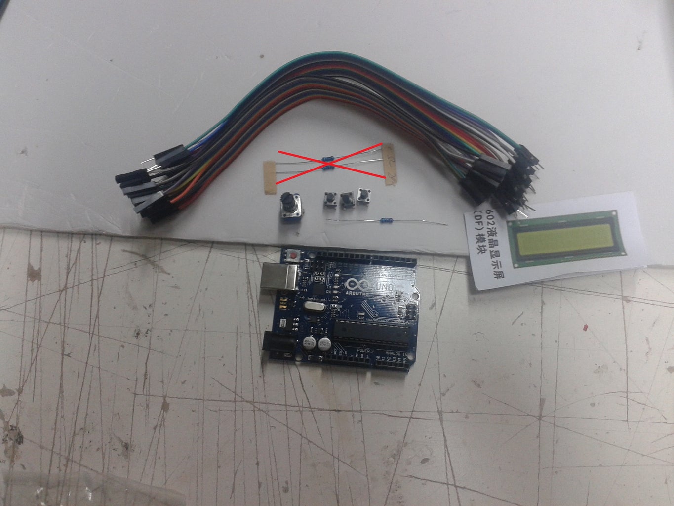
Option 1
1 x Arduino UNO
1 x 16x02 LCD screen
1x 10K potentiometer
1x 330 ohm resistor
3x Push buttons
Jumper cables
1x I2C level shifter (not on materials picture)
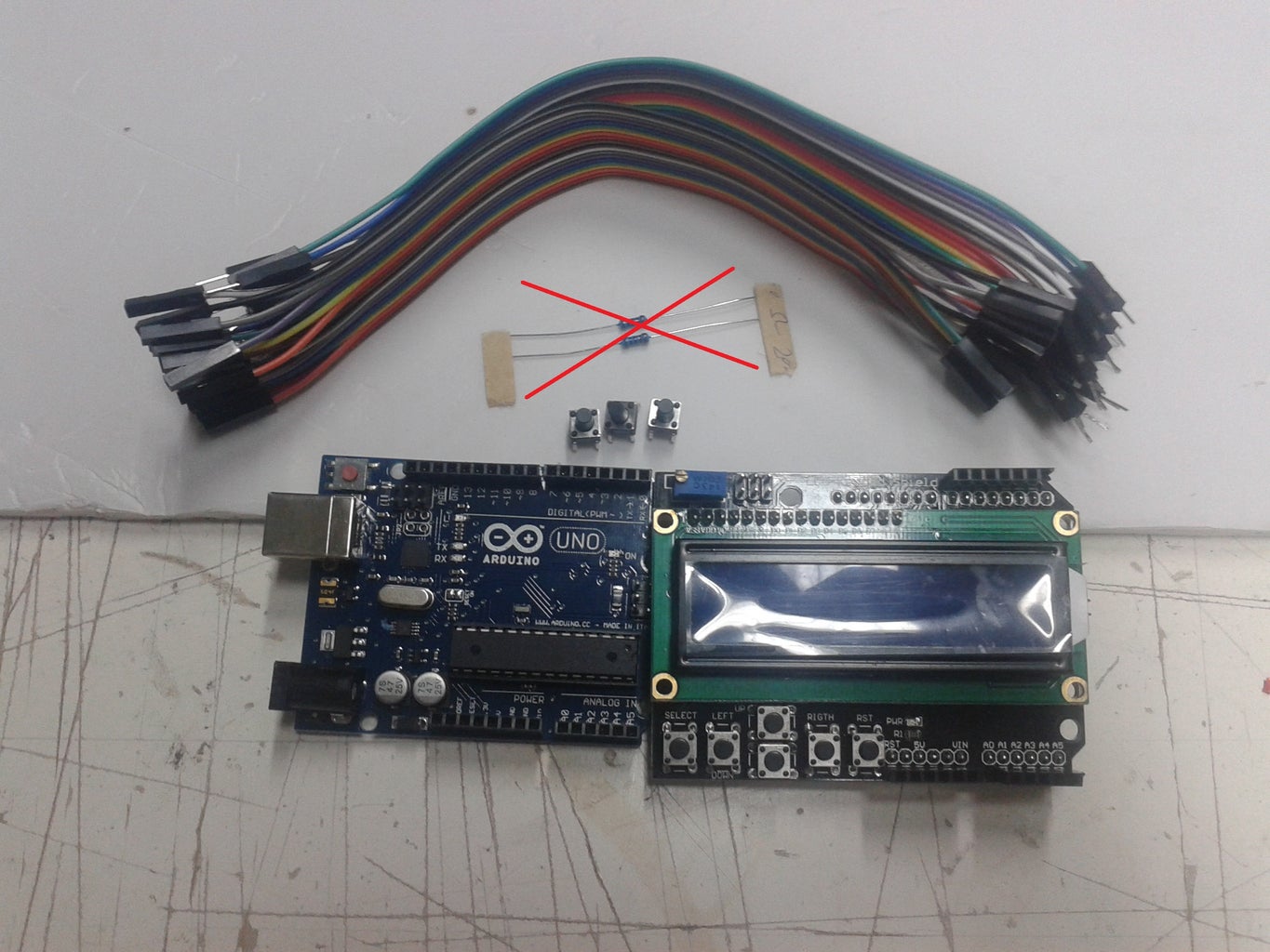
Option 2
1 x Arduino UNO
LCD Keypad Shield (the buttons on the shield will not be used)
3x Push buttons
Jumper cables
1x I2C level shifter (not on materials picture)
Option 2 is the one that will be built because that is what I had at hand at the moment. The level shifter is an important part of the circuit as nowadays most devices use 3.3V logic and the 5V from the Arduino damages them.
(On the pictures, the crossed out material is not required.)
Step 2: Circuit


The circuit is pretty straight forward, using the standard pinout for the Arduino examples for the LCD, the default pins for I2C and 3 spare pins for the pushbuttons.
In case you use the LCD Keypad Shield, the pinout for the LCD changes but that is already considered within the code. The LCD Keypad Shield buttons are not used because they require an analog polling method that breaks compatibility between the two possible implementation circuits (Shield and stand alone LCD)
Step 3: Code

In case the LCD Keypad Shield is used, #define LCD_SHIELD must be left uncommented at the beginning of the sketch. Otherwise, comment it to use the first diagram.
Attachments

Step 4: Conclusions

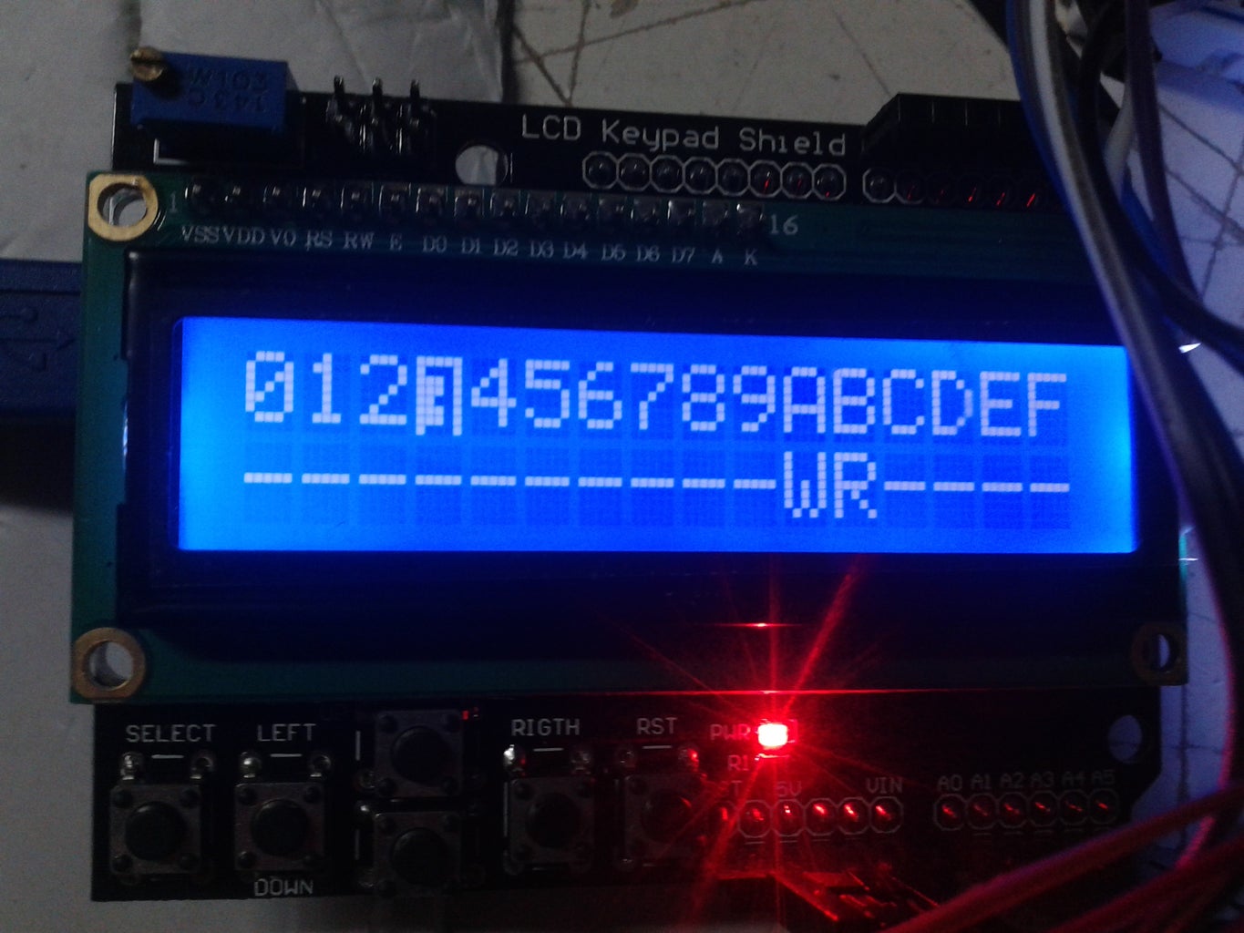
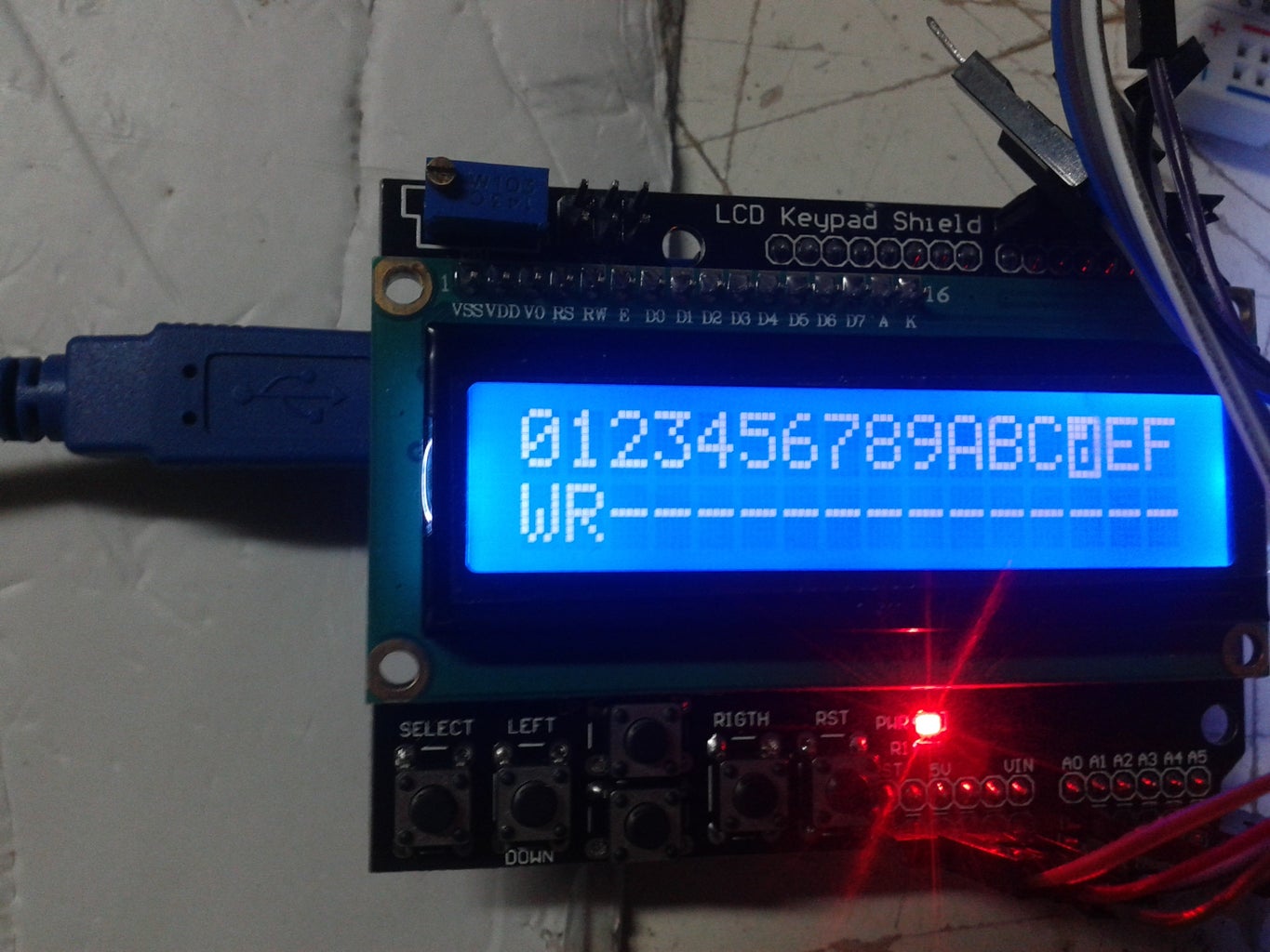
For testing the code and circuit, a BQ32000 RTC chip and a MMA8452Q accelerometer were used. As can be seen on the pictures, the device is detecting 4 addresses: 0x3A and 0xD0 as write addresses, and 0x3B and 0xD1 as read addresses. This addresses correspond to the test devices so the code is working.
I would like to thank the kind girls at Beijing Makerspace, Fu Yao and Liu Xin, for helping me get the materials required for testing this project on such a short notice.

Participated in the
Microcontroller Contest


