

Introduction: Arduino Leonardo As ISP


The Leonardo was my first Arduino, I bought it because it's native USB capabilities. After experimenting with Arduino, I decided to migrate from my Arduino Leonardo to a standalone Atmega328p or, for smaller projects, to a microcontroller from the Attiny family.
After some research I found this guide by PeterVH: http://petervanhoyweghen.wordpress.com/2012/09/16/arduinoisp-on-the-leonardo/
After several failed attempts, I was able to burn the bootloader and upload sketches successfully and wanted to share that with this Instructable.
Disclaimer
I can not be held responsible for any damages that could occur to you or your equipment while following the procedures present on this page. Also, I give absolutely no warranty on the correctness and usability of the information on this Instructable. Please note, however, that these procedures have worked in my case without any damages or problems.
Step 1: Materials

- Arduino Leonardo (with usb cable)
- A computer (all steps are based on computer running Windows)
- Wires
- Target Atmel microcontroller
Step 2: Preparing the Leonardo


I am assuming that you have already installed and configured the IDE, and you've been able to upload sketches before (If you don't :http://arduino.cc/en/Guide/HomePage).
1- Open Arduino IDE
2- Open the ArduinoISP sketch (File/Examples/ArduinoISP)
3- Change the following lines (see picture 1):
#define RESET SS TO #define RESET 10
#define LED_HB 9 TO #define LED_HB 13
( we want to use digital pin 10 to reset the target and we are setting the heart beating led on pin 13)
4- Save the sketch as LeonardoISP (so you can use it later)
5- We choose Arduino Leonardo (Tools/Boards/Arduino Leonardo) and the appropriate Serial Port (Tools/Serial Port/COM **)
5- Upload
If the sketch was uploaded correctly, you will see the on-board led (the one marked as L) doing a heartbeat sequence.
Now, on your Arduino IDE folder:
1- Create a new folder in "hardware" with the name of leofix
2- Open a text editor and paste this code (picture 2):
arduinoispleo.name=Arduino as ISP (Leonardo)
arduinoispleo.communication=serial
arduinoispleo.protocol=arduino
arduinoispleo.speed=19200
Save the file as programmers.txt (see picture 3)
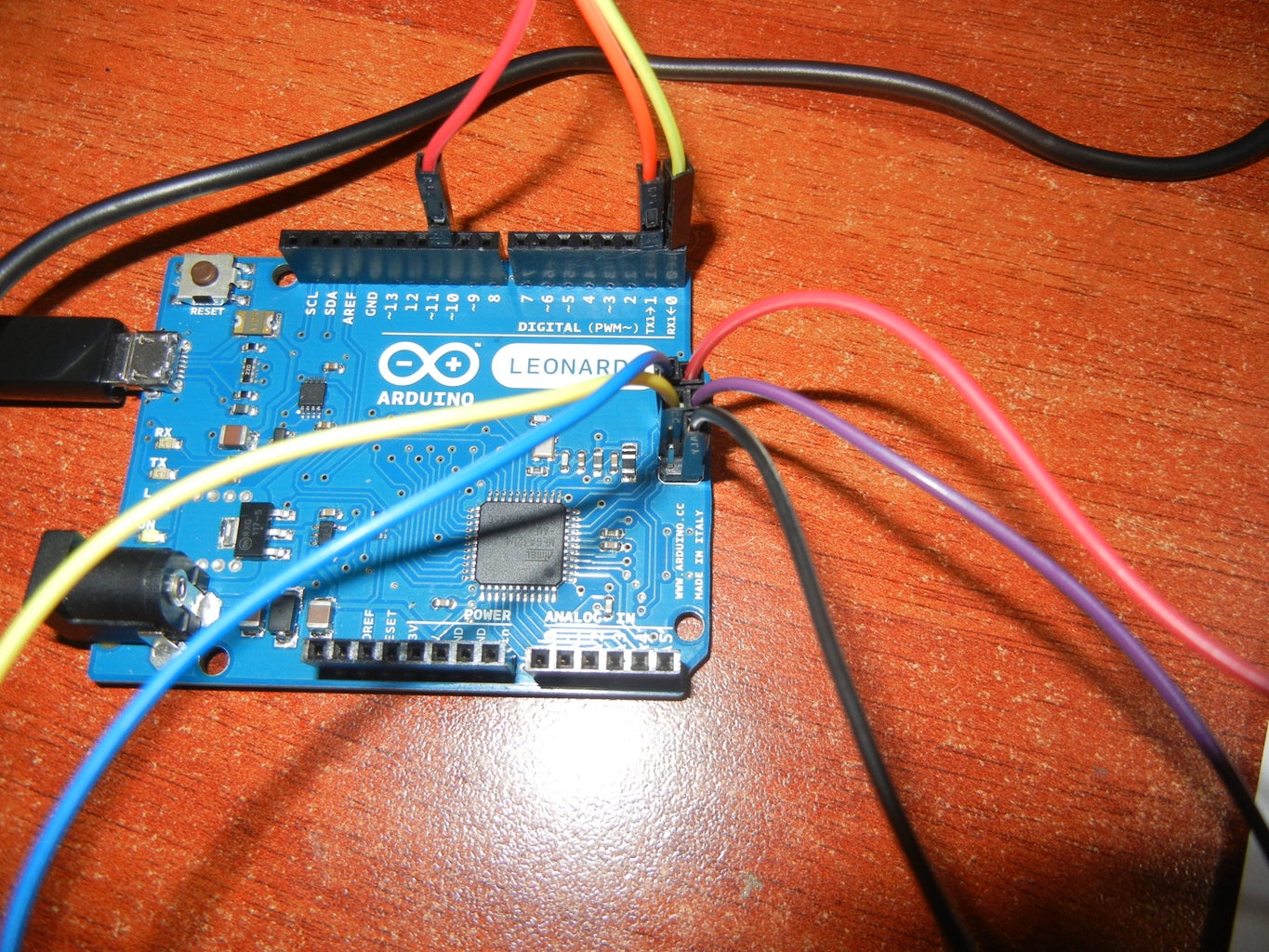
Next we connect some wires to our Leonardo (picture 4):
Digital Pin 10,1(TX),0(RX)
ICSP MISO,5V,SCK,MOSI,GND (see 6pin pinout on picture 5)
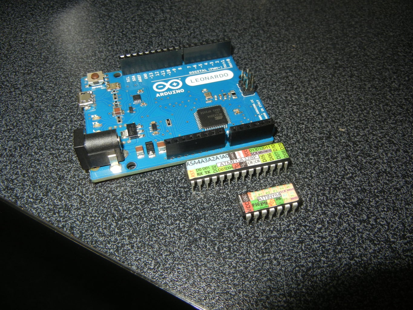
Step 3: Target Atmel Microcontroller 1: Atmega328p (materials)

The steps featuring the Atmega328 can be used for Atmega168 and the Atmega8(not tested)
You need this:
(Source: http://arduino.cc/en/Tutorial/ArduinoToBreadboard)
For external 16Mhz crystal configuration:
-Atmega328p
-10k Ohm resistor (I used 22K) x1
-16 MHz clock crystal x1
- 22 pF capacitors x2
(or you could just buy any of these kits, like I did:
Virtuabotix Bareduino - Bare minimum 16 MHz Arduino Kit
Virtuabotix Bareduino Plus- Arduino Compatible Microcontroller with Power Regulator
Both are bootloaded as Duemilanove, so you save a step)
For Minimal Circuit (Eliminating the External Clock) configuration:
-Atmega328p x1
Step 4: Target Atmel Microcontroller 1: Atmega328p (assemble)


For external 16Mhz crystal configuration:
See picture 1
Also you can follow this guide:
https://www.virtuabotix.com/product-bareduino328-barebones-microcontroller-guide/
For Minimal Circuit (Eliminating the External Clock) configuration:
Only place the Atmega on your board (picture 2)
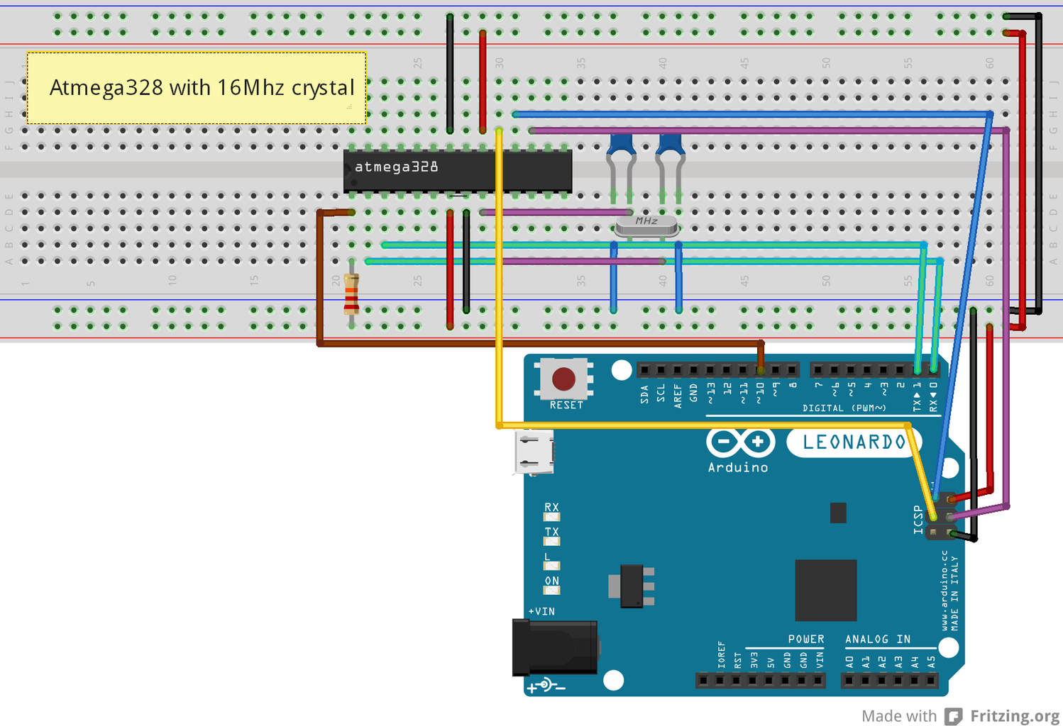
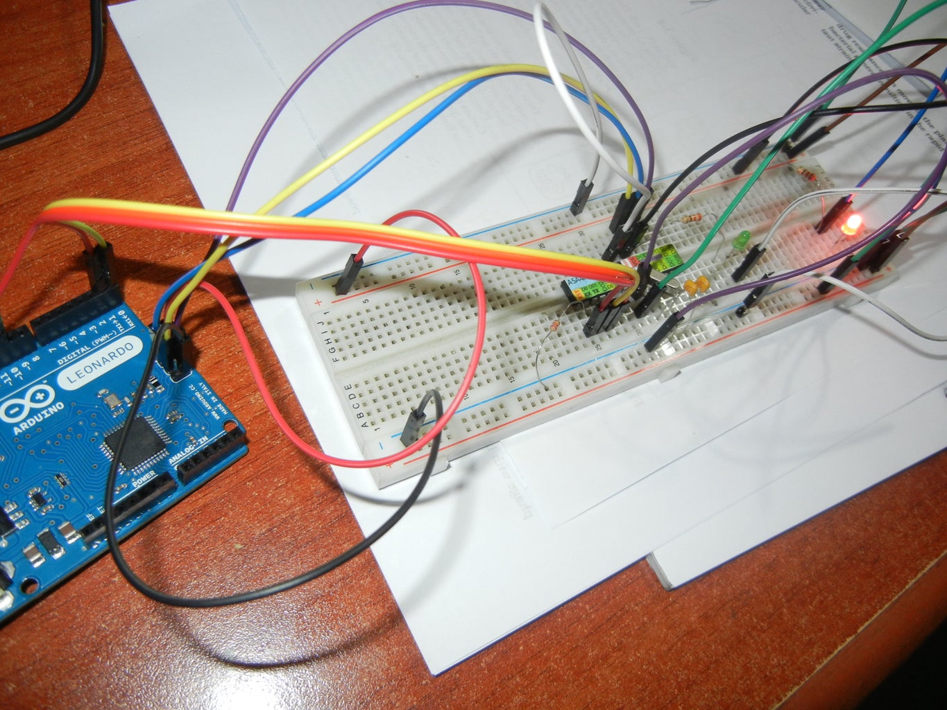
Picture 3 and 4---Atmega328 with external 16Mhz crystal
Picture 5 Atmega328 minimal circuit
Step 5: Target Atmel Microcontroller 1: Atmega328p (burning Bootloader and Uploading Sketches)


For external 16Mhz crystal and Minimal circuit configuration:
1- Connect the wires from the Leonardo to the atmega328 (please take a look to atmega328 pinouts these are the same with atmega168 -picture 1):
Atmega328 Arduino Leonardo
(in the picture 1 pins on black)(picture 2- 6pin ICSP)
RX pin 2-------------------------------------digital pin 0
TX pin 3-------------------------------------digital pin 1
MISO pin 18-----------------------------------ICSP pin MISO
MOSI pin 17-----------------------------------ICSP pin MOSI
SCK pin 19-----------------------------------ICSP pin SCK
RESET pin1-------------------------------------digital pin 10
And power pins 5v and ground.
Refer to pictures 3 and 4 for the final result
Burning Bootloader (if you bought the Bareduino or you are using a bootloaded Atmega328 skip this step)
*********IMPORTANT: additional step for Minimal circuit configuration*********
1- Go to http://arduino.cc/en/Tutorial/ArduinoToBreadboard and download the Breadboard.zip
2- Create a "hardware" sub-folder in your Arduino sketchbook folder (whose location you can find in the Arduino preferences dialog). If you've previously installed support for additional hardware configuration, you may already have a "hardware" folder in your sketchbook.
3-Move the "breadboard" folder from the zip archive to the "hardware" sub-folder of your Arduino sketchbook.
4-Restart the Arduino software.
5-You should see "ATmega328 on a breadboard (8 MHz internal clock)" in the Tools > Board menu.
******************Additional step finish here******************
1- Check the connections again
2- Select your board:
Atmega328 with external 16mhz crystal ----> Arduino Duemilanove w/ATmega328
Atmega minimal circuit without external crystal -----> ATmega328 on a breadboard (8 MHz internal clock)
3- The Serial Port should be the same as Arduino Leonardo
4- Select Arduino as ISP (Leonardo) in Programmer
5- Select Burn Bootloader at Tools Menu
6- If you get this message: Done burning bootloader, Success! (see pictures 6 and 8)
If you receive an error message, check your connections one by one and repeat the process.
Upload a sketch
1- Do not move your connections
2- Choose a sketch (look at picture 1, Arduino pin configuration in red)
3- Use Upload using programmer from the File menu, Done! (picture 9-classic blink)
If you receive an error message, check your connections one by one and repeat the process.
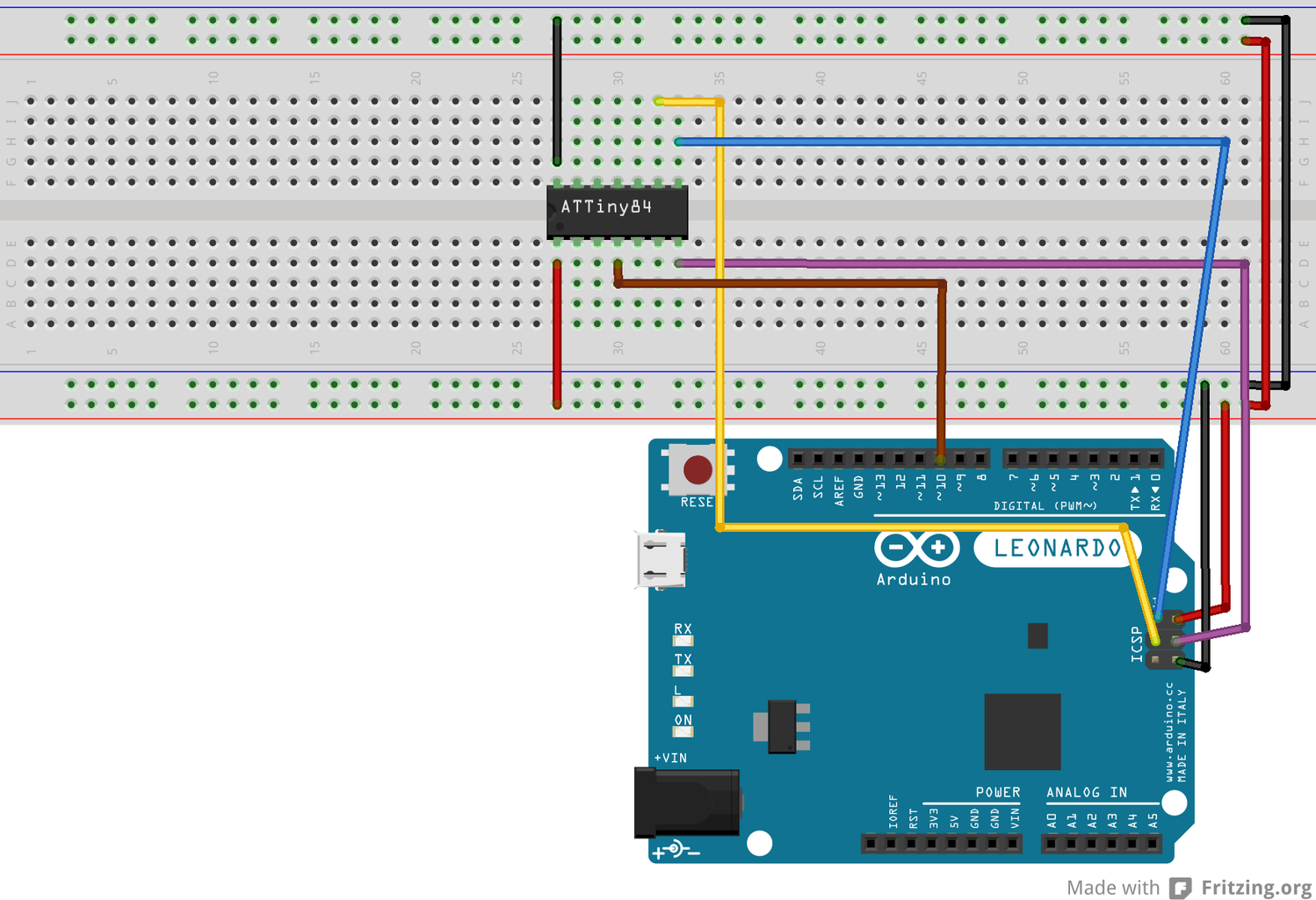
Step 6: Target Atmel Microcontroller 2: ATtiny84


These instructions are not only for the ATiny84, they should work for Attiny45, Attiny85, Attiny44 and Attiny84 using the High-Low Tech Core, and for ATtiny84 (84/44/24), ATtiny85 (85/45/25), and ATtiny2313 (4313) using the Arduino-Tiny Core, but finally, the process is the same.
1- Install the software support for the Arduino IDE from the core you chose.
2- Plug wires between (RX,TX, if available) MISO, MOSI, SCK,RESET, 5V and GND of the ATtiny (search for pinout from the Atmel datasheet) and your Arduino Leonardo.
REMEMBER: the RESET pin for the Leonardo is digital pin 10
3- Open a sketch
4-Choose the corresponding board. In my case, using the High-Low Tech Core, I am selecting Attiny84 (internal 8Mhz clock).
5- Select Arduino as ISP (Leonardo) in Programmer.
6- Use Upload using programmer from the File menu.
Important: Some chips have to be bootloaded when using the Arduino-Tiny Core. In that case use Burn bootloader before you upload a sketch.
Important, also: Cores use different pin configuration, you have to refer to their documentation when writing a sketch.
Example:Picture 2 is Pin configuration for ATtiny84 from the High-Low Tech Core and picture 3, from Arduino-Tiny Core.
Step 7: Thanks!
This is my first Instructable so any comments, suggestions, criticism are welcome.

Participated in the
Arduino Contest


