

Introduction: Arduino Lilypad Interactive Passion Sensing Scarf


This was my first time working with an Arduino Lilypad. I have been wanting to try something that dealt with soft circuits for awhile now. This project is what I came up with. The concept is based off my friend Ethan Dicks from theFusefactory.org's emergent Sheep Sculpture project.
The Lilypad Interactive Passion Sensing Scarf works like so:
Scarf number one being worn by someone walking alone will light up with the color Blue for Lonely. When the wearer of scarf number two joins up with number one, the two scarves will sense each other and then light up Red for Love.
Future plans for capacitance touch: which will allow the colors to Pulsate for Passion if one wearer touches the other wearers scarf.
Below is a video so you can see how it works. Please note this is a work in progress, I only have the electronics embedded into one scarf right now. I am still working on and perfecting these. Please fill free to share your ideas!
Step 1: Materials

Here is a list of the items you will need to complete this project. For the Lilypad items, I purchased everything from FunGizmos.com. You will need two of each to make two scarves.
Savings Tip: If you need to save money, you could have one of the scarves work just as an emitter only, which would only need the IR transmitter and a battery.
Electronic Components
1. Lilypad Arduino Board
2. Lilypad Tri-Color LED
3. Coin Cell Holder
4. 3V Coin Cell Battery 20mm
(or you can use any of the other power and battery boards for the Lilypad)
5. Conductive Thread
6. Lilypad Button Board (optional)
7. (x2) Infrared Emitter and Phototransistor Detector - available at RadioShack
8. Resistors 10Kohm and 56ohm
9. FTDI Basic breakout Board (used to program the Lilypad)
Scarf Components - For the fabric needs, I went to my local craft store.
1. I used two different colored fleece scarves
2. Two different fabric prints ( I had 1 yd of each)
3. Heat'n Bond Ultra Hold Iron-On Adhesive
4. Fabric paint
5. Iron Patches (optional)
Step 2: Pattern Creation


For my scarves, I wanted flames for the designs. I used a old file folder and drew out the flame shapes on it to use as a pattern.
Once I had my pattern shapes, I used the fabric adhesive and ironed it onto the underside of the fabric. The adhesive has a paper back on one side (you want this side up).
With the adhesive now on the fabric, I traced my flame onto the paper side and then cut out the shape. Do not remove the paper yet! Keep this on until you are ready to iron it on to the scarf.
Tip: Iron on the adhesive before cutting your fabric pattern shapes. This will keep your fabric from frying!
Step 3: Sewing Electronics


The MakeZine has a really great video tutorial by Becky Stern on getting started with the Lilypad. This is what I referred to when I got started with this project.
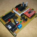
As you can see in the first picture, I had the power circuit board too close to the Lilypad. I later had to move this once I started sewing my circuit traces.
The actual circuit is pretty simple. Connect Positive Power and Ground from the Battery to the Lilypad. Then the pin outs are as follows:
int statusPin = 13; // onboard status LED is connected to digital pin 13
int redPin = 11; // R petal on RGB LED module connected to digital pin 11
int greenPin = 9; // G petal on RGB LED module connected to digital pin 9
int bluePin = 10; // B petal on RGB LED module connected to digital pin 10
int sensorPin = 5; // IR phototransistor connected to digital pin 5
int irPin = 6; // IR LED connected to digital pin 6
NOTE: complete Arduino sketch is at the end of this Instructable
TIP: You can use some of your scrap pieces of fabric to hold down your circuit traces. It's important that they do not cross or touch each other so that you do not create a short.
TIP: As you can see, the underside of your scarf will look kind of ugly with the circuit traces running through. You can cover this up by either sewing another scarf on top (leaving an opening to program your Lilypad) or by cutting out a scarf from the extra fabric you used for your pattern shapes.
Step 4: Infrared Emitter and Phototransistor


The IR Emitter is the one that is tinted in color, and the Phototransistor (detector) is the one with the clear package.
You will need to add some resistors to the emitter and detector. I used a 10Kohm resistor (brown, black, orange) on the detector and a 56ohm resistor (green, blue, black) for the emitter.
In order to hide the components since the emitter and detector will be on the front of the scarf, I used an iron-on patch. I curled the leads of each of the emitter and detector, then used an exacto knife and cut an "X" slit into each of the eyes. This allowed me to push the emitter and detector through the patch.
Hook-up: The emitter and detector each get hooked up from POWER to RESISTOR to LILYPAD PIN to IR LED to GROUND. Refer to the schematic on this step for better understanding. More information on pull up resistors by Make Online.
NOTE: Full schematic is at the end of this Instructable.
TIP: You wont be able to see the IR LED's light up. If you view them through your digital camera you will be able to. You will notice in my video that you can see the emitter is lighting up.
Step 5: Iron-on Patterns


Once you are ready to iron-on your patterns. Set the iron to medium heat with NO steam. Peel of the paper backing and arrange your patterns where you would like them located on the scarf.
I made sure on mine that I was able to hide any of the conductive thread that would be seen.
Depending on your scarf fabric, you don't want to hold the iron too long in one place. I used fleece so I had to move quick and press down quickly in order to keep from melting and/or burning the fabric.
Once everything has been ironed onto the scarf, I went around the edges using fabric paint. This helps to serve two purposes. It helps to keep the fabric secure and also adds a little pop to the shapes.
TIP: Let the fabric paint dry over night in a warm area. This will help the paint dry. If you had this in a cold garage or something then the paint will later crack.
NOTE: If you are handy with sewing or a sewing machine, you can sew down the patterns. I am not to that level yet so this was the easiest way for me to do it.
Step 6: Arduino Sketch

/*++  Sheep -  Use a combination of RGB and IR LEDs and a photosensor to imitate           crowd-reactive (emergent) behavior  This code goes with the Fuse Factory Workshop "Make an Emergent Behavior Sculpture  With The Arduino"  http://thefusefactory.org/2009/09/03/make-an-emergent-behavior-sculpture-with-the-arduino/  The scultpture, or "sheep", is an artistic assemblage of a Lilypad Pro kit (Lilypad  base attached to a Lilipad 5V power unit) with a tri-color LED mounted over the 328V  MCU on the Lilypad board.  A Large Lilypad Protoboard sits between the PSU and the  Lilypad itself to route power and to hold resistors and the IR components.  The illusion  of a quadraped is completed by 1W and 2W LEDs soldered to the PSU "body" and bent as legs.  The code depends on a persistent variable called "mood" - when it is zero or near zero,  the sheep is "happy".  Below zero and the sheep is "lonely"; above zero and the sheep  feels crowded or agitated.  Loneliness is represented by blue, happiness by green, and  agitation by red.  In between expressing "mood" (using PWM to shade the RGB LED), the  main part of the code checks for IR pulses from other sheep and may emit its own pulses  to "call out" to other sheep.  By tweaking internal variables, the sheep can be more or  less sensitive to the calls of other sheep.  The emergent behavior comes out when  multiple sheep are assembled and placed on a table, calling out to each other.  The  flurry of IR pulses can induce the sheep to be happy or perhaps agitated.  Few pulses  and the sheep exhibits loneliness.   Sheep.pde - turn an Arduino into an emergent behavior sculpture    Copyright (C) 2009, Ethan Dicks    This program is free software: you can redistribute it and/or modify    it under the terms of the GNU General Public License as published by    the Free Software Foundation, either version 3 of the License, or    (at your option) any later version.    This program is distributed in the hope that it will be useful,    but WITHOUT ANY WARRANTY; without even the implied warranty of    MERCHANTABILITY or FITNESS FOR A PARTICULAR PURPOSE.  See the    GNU General Public License for more details.    You should have received a copy of the GNU General Public License    along with this program.  If not, see .--*//*++  Variable initialization - before the code start, put all of the user-adjustable                            parameters at the top so they are easy to tweak.--*/// Definitions of "mood" values
#define MOODMAX 80
#define MOODMIN (-1 * MOODMAX)

#define LONELY (MOODMIN)
#define HAPPY (0)
#define CROWDED (MOODMAX)
#define MSTEPS 5

#define BLEAT_VOLUME 1

// Global definitions of pin assigments (to simplify individual function calls) int statusPin = 13; 	// onboard status LED is connected to digital pin 13int redPin    = 11; 	// R petal on RGB LED module connected to digital pin 11int greenPin  =  9; 	// G petal on RGB LED module connected to digital pin 9int bluePin   = 10; 	// B petal on RGB LED module connected to digital pin 10int sensorPin =  5;     // IR phototransistor connected to digital pin 5int irPin     =  6;     // IR LED connected to digital pin 6// Start off expecting to be happy	 int mood = HAPPY;

// Keep track of the sense of the input pinint eye = 0;

// And remember how "loud" we are "bleating" (flashing our IR LED)int bleat = BLEAT_VOLUME;

/*++  setup() - The Arduino environment will call the code in setup() one time            only, right after the board is reset.  Put code in this function to initialize I/O pins and such - things that  only need to be done once during a run.--*/voidsetup()
{

  // for debuggingSerial.begin(9600);
  Serial.println("Sheep v0.02");

  // Mostly, our I/O pins are outputs to LEDs  pinMode(statusPin, OUTPUT); 	// sets the statusPin to be an outputpinMode(redPin, OUTPUT); 	// sets the redPin to be an outputpinMode(greenPin, OUTPUT); 	// sets the greenPin to be an outputpinMode(bluePin, OUTPUT); 	// sets the bluePin to be an outputpinMode(irPin, OUTPUT); 	// sets the irPin to be an output// One exception is the IR phototransistorpinMode(sensorPin, INPUT); 	// sets the sensorPin to be an inputSerial.print("Setting IR 'bleat' to ");
  Serial.println(bleat);

  analogWrite(irPin, bleat);

}

/*++  loop() - the Arduino environment will call the code in this loop forever.  Put interesting things in here that are meant to run endlessly after setup()  is called once.  The only way out of this loop is to reset the board.--*/voidloop() 	// run over and over again
{
  // Set our RGB LED to reflect our "mood", which will hopefully change from time to time
  set_mood(mood);

  // Slow down how fast we react to other 'sheep'delay(100); 	// delay for .1 second// sensorPin has a 10K pullup resistor, so *no* light reports a 1.  We need to// invert the logical sense of the pin if we want to think of the light logically// as 1-is-on/0-is-off
  eye = 1 - digitalRead(sensorPin);    // set eye to 1 if we "see" any IR light// Report our present status everytime through the loop  Serial.print("Mood is ");
  Serial.print(mood);
  Serial.print(".  Sensor is ");
  Serial.println(eye);

  // If we see pulses from another 'sheep', increment the mood, but not past MOODMAXif (eye) {
    // since humans cannot "see" infrared light, use the status LED as a visible indicatordigitalWrite(statusPin, HIGH);  // echo IR input detection on the status LED
    mood += MSTEPS * 2;
    if (mood >MOODMAX) {
      mood = MOODMAX;
    }
  }
  // If we don't see any IR pulses, decrement the mood, but not below MOODMINelse {
    // since humans cannot "see" infrared light, use the status LED as a visible indicatordigitalWrite(statusPin, LOW);  // echo IR input detection on the status LED
    mood -= 1;
    if (mood < MOODMIN) {
      mood = MOODMIN;
    }
  }
}

/*++  set_mood - convert "mood" to a color scheme  Mood varies from some negative number to that same value as a positive number  (so far, -80/+80 and -100/+100 produce reasonable results).  Proportionally, the continuum of mood to color mapping resembles the following:                    Mood  -100                0                +100  Lonely     ->     Happy      ->     CrowdedR   0        0        0        30       100G   0        30      100       70        0B  100       70       0         0        0--*/void set_mood (int mood)
{
  // Start out with each color being off - adjust upwards based on "mood"unsignedchar redness   = 0;
  unsignedchar greenness = 0;
  unsignedchar blueness  = 0;

#ifdef DEBUG
  Serial.print("Mood is ");
  Serial.println(mood);
#endif

  // blueness is all about mood being less then happy if (mood < HAPPY) {
      blueness  = abs(mood);
      greenness = MOODMAX + mood;
  }
  // redness is all about mood being more than happyelseif (mood > HAPPY) {
      redness   = mood;
      greenness = MOODMAX - mood;
  }
  // greenness is about mood being around happyelse {
      greenness = MOODMAX;
  }

  // Set the LED to reflect our present mood
  color(redness, greenness, blueness);

}

/*++  color(r, g, b) - set the tri-color LED to the requested color value  Uses analogWrite(pin, value) to set PWM value for each individual LED color  The Tri-color LED is a common-anode device, so to make light, we ground the  desired pin.  To invert the PWM waveform, we subtract our desired intensity  from 255, so that, for example, if we want red off, logically, we pass around  a value of zero, but set the PWM value to 255 so that the pin is driven high  100% of the time.  To get red to the maximum brightness, we pass around a  logical value of 255, but set the PWM value to 0, pulling that pin low 100%  of the time.--*/void color (unsignedchar red, unsignedchar green, unsignedchar blue)     // the color generating function
{
#ifdef DEBUG
  Serial.print("color(");
  Serial.print(red,HEX);
  Serial.print(blue,HEX);
  Serial.print(green,HEX);
  Serial.println(")");
#endif

  // invert the sense of the PWM value when calling analogWrite() for each coloranalogWrite(redPin, 255-red);
  analogWrite(bluePin, 255-blue);
  analogWrite(greenPin, 255-green);

}
Step 7: Schematic
Schematic is attached to this step as an Adobe PDF file. This was the original sheep file, but I set the scarves up using the same method.
If you add to this idea, which I hope some will... email me, I would love to see what others have added.
- Think It - Build It - Share It -
http://www.ArduinoFun.com


