

Introduction: Arduino Magic Clock


What if a clock could tell you more than just the time? In this Instructable we are going to make a clock that, with just a glance, can tell someone where you are and just to spice things up the temperature of your surroundings. Alright, grab your Arduino and lets get started :)
Things you will need for this Instructable:
- Arduino
- Breadboard
- Wires
- Wood (Balsa or even cardboard)
- Servo
- Temperature Sensor
- Resistors
- Hot Glue
- Glitter
- Paper
Step 1: Prototyping Clock Design
Begin your design by writing down the places you are most likely to be during the day. These will be the first few positions on the clock, then add in a few fun ones to make your clock unique. I added "Mortal Danger" and "Lost" to my clock. Now, think of 5 words to describe temperature, from super cold to super hot. I used "freezing", "chilly", "just right", "warm" and "swelter".
Next, I went about designing my prototype in Illustrator. If you would like to use my template please feel free to download the attached file. I cut out the paper prototype with an Xacto knife and traced the outside circle onto a piece of wood. My clock will have a diameter of about 12 inches. If your printer cannot handle the whole clock face in one go, just tape two halves of the picture together and mark your hole positions.

Attachments

Step 2: Cut Paint Clock Face
Use an X-acto or saw to cut the outside profile of your clock and a 3/4" drill bit to cut out the holes. I then used painters tape to section of the top half and spray painted it blue. Once it was dry I reversed the tape line and spray painted the bottom half silver. While everything is drying use your X-acto knife to cut out the position locations for your clock.


Step 3: Decorate Clock Face

Now that our positions have been cut out, flip them over, rub on some glue, center them onto the face of the clock and press them down.


I may have gotten a bit to fancy at this part, but I thought "you know what would make this clock more magical.....glitter!" So I ran beads of glue around the edges of the clock positions and then sprinkled copious amounts of glitter on top. Once you shake it off it will leave a nice shimmery border around your lettering.
Step 4: Adding Servo Motor

I needed to adjust the hole size in the center of the clock to accommodate the servo, a drill and file makes short work of this process. Next, hot glue in the servo motor. Its very important to keep the servo at 90 degrees to the front face so your clock mechanism will not scrape on the clock face. I held the servo in the proper position until the glue dried.
Step 5: LED Extensions
We are going to need to extend the legs of the LED so they can easily plug into our breadboard. To do this we are going to twist the wires together and then electrically connect them with solder. Begin by stripping both ends of the wires with the universal stripper. Next twist the wires together to form a strong mechanical lock, you should be able to lightly tug on the wires without them coming apart. Don't hesitate to use pliers to help get a couple more twists. Then use your iron and solder the wires together.


Step 6: Add LED's to Clock

With all the LED's soldered lets add them to the back clock. I bent the leads at the base of the LED's 90 degrees and using the hot glue gun secured them in the center of the five temperature cutouts.
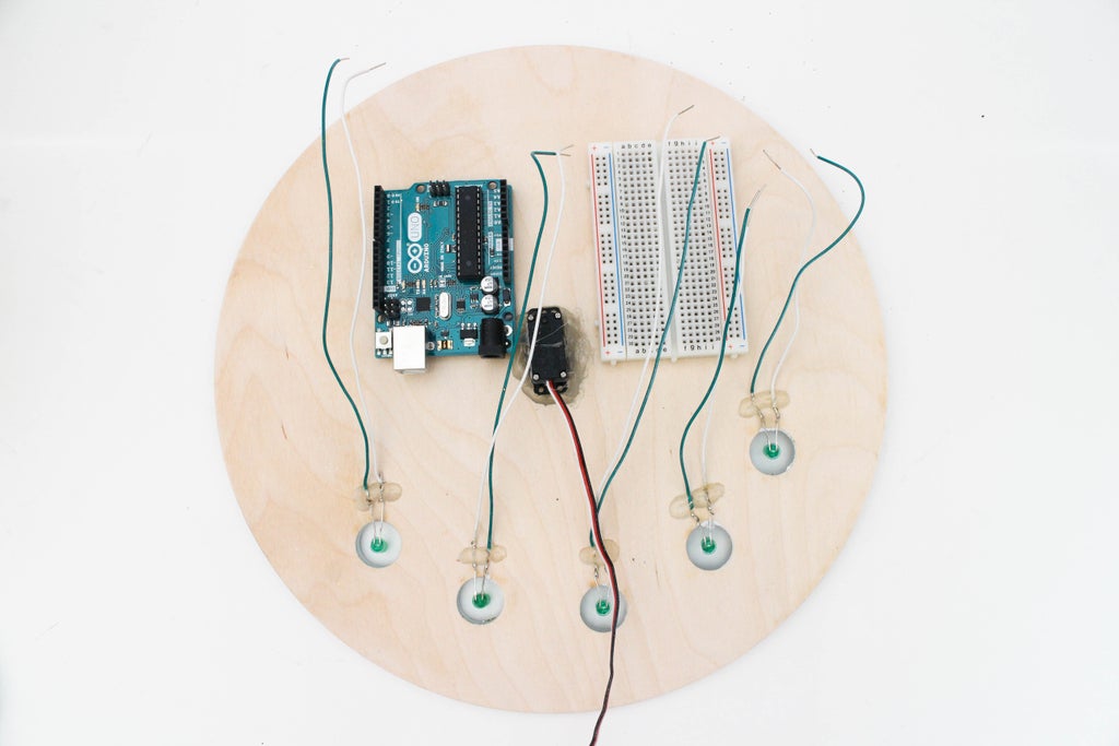
Step 7: Wiring Up LED's Part 1

Using double stick tape I fastened down the Arduino and breadboard onto the back of the clock. To begin wiring up the LED's I put all of the ground wires (green wires) into the negative column of the breadboard. Then I plugged in all of the power wires in order into the breadboard.
Step 8: Wiring Up LED's Part 2

Now add another wire from all the positive LED's leads to the Arduino. I used pins 4 through 8 for this, but you can of course use any pins you wish.

Step 9: Wiring Servo Motor

Begin by plugging in the servo power wire into the 5V pin on the Arduino. Then plug in black wire to GND and the signal cable (your might be white or orange depending on your servo) into a pin with PWM capability, I used pin 3. Once you have your servo plugged in and your LED's plugged in add a wire form the Arduino GND to the ground rail being used by all the LED's.

Step 10: Adding Temperature Sensor
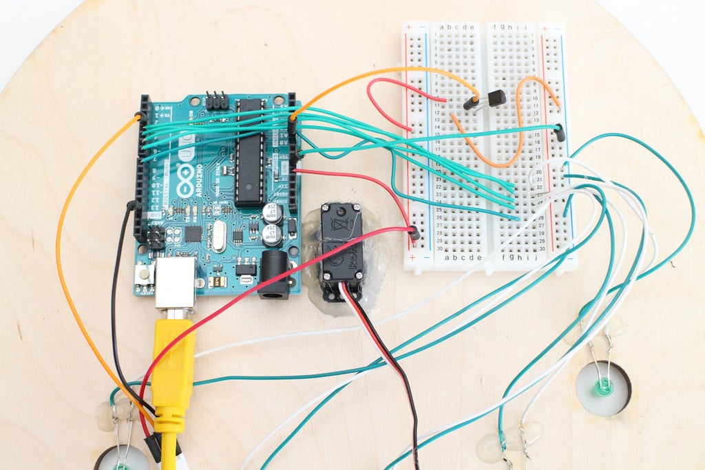
This temperature sensor works by changing voltage depending on the temperature in the room, very similar to the way the light sensor would change voltage based on how much light was in the room. To wire up the temperature sensor begin by placing a wire from the middle leg, which is signal, to the A0 pin. In my circuit the signal wire is orange.

Then you are going to want to add power and ground to the sensor. This will require a slight modification to the servo motor circuit. Instead of plugging in the servo power directly into the 5V pin on the Arduino, run a wire from 5V power to the breadboard and then plug both the temperature sensor and the servo into the same row. If your circuit looks similar to the one below you're on the right track.
Step 11: Attach Clock Hand

Now that all of the circuitry for this project is done lets flip over the clock and work on the face. To make the clock hand I started by trimming down a clock hand off an old clock I found. Wear your safety glasses while doing this just incase :) Next grab your hot glue gun and put a thin bead of glue on the servo motor attachment, and then quickly attach the clock hand.
Step 12: Coding Part 1
We begin our coding with a standard but slightly larger initialization of the 5 LED's, Servo, and temperature sensor. Additionally, we create place holder variables for the servo clock position and the temperature variable which I am calling initialTemp. Notice that this is labeled as a float and contains a number with a decimal point, this will give us more resolution on temperature measurements
#include Servo myservo;
int clockPos = 0;
int tempSensorPin = A0;
const float initialTemp= 20.0;
int tempLED1 = 4;
int tempLED2 = 5;
int tempLED3 = 6;
int tempLED4 = 7;
int tempLED5 = 8;
Besides a lot of setting up pinModes we will need to attach the servo we connected to the Arduino to its software include library. I've attached the servo to pin three so using the function myservo.attach(3) will let the Arduino know which pin should be PWM.
void setup(){
  Serial.begin(9600);
  myservo.attach(3);
Attachments

Step 13: Coding Part 2
To make controlling the clock hand easier we are going to program the Arduino to label the possible positions on the clock (ex: work, traveling etc.) with numbers from 0 to 6. Using the Serial.parseInt() command makes short work of understanding the numbers we are sending to the Arduino. To trigger the actual motion of the hand we check to see if the enter key has been hit, remember the invisible "\n" that gets sent, we are now going to check the end of our message and if its found we will write a new position to the servo.
if (Serial.available()>0){
    int clockPos = Serial.parseInt();
    if (Serial.read() == '\n'){
      myservo.write(clockPos*25+((clockPos+1)*3));
      delay(200);
    }
  }
The math I used to get the clock position angles down took a lot of tweaking but it comes down to multiplying the number we entered (clockPos) by 25 and then figuring out the proper offset to get the arrow pointed close to the center of the position logo on the clock face. For me I added one and then multiplied by three to get a good looking offset. Lets run through the math with some real numbers to show you how this works.
Servo Position Math
Using my clock positions lets assume I want so show that I am "Traveling". This would be represented by the number 2, where 1 was "Mortal Danger" and 0 was "Work".
So our clockPos = 2 therefore:
Servo Angle = (2*25)+((2+1)*3)
Servo Angle = 59 degrees
To the Arduino once it solves the math the servo write line looks like this now, which is exactly that we want.
myservo.write(59);
Step 14: Coding Part 3
In the next code block we are going to head back into the main loop and analog read the temperature sensor, a short delay ensures that the value has time to settle. Then to convert the voltage being read into temperature we divide the number we are getting from the ADC by the maximum value of 1024 and multiply by 5V. This gives us the temperature sensor value in volts. To get it into degrees we subtract by .5 and then multiply that whole thing by 100. Whew! That was complicated but we are almost done.
int tempVal = analogRead(tempSensorPin);
delay(10);
float temp = (((tempVal/1024.0)*5)-.5)*100 ;
Serial.println(temp);
To finish off coding the temperature sensors we are going to create a switch case for each LED light using a lot of the same code and functions we used before. The one addition we are going to make is mapping the temperature in the room to a number from 0 to 4. This will allow us to easily use the switch case to control the LED's.
int switchcase = map(temp, 12, 28, 0, 4);
Serial.println(switchcase);
Step 15: Upload Code & Test

Phew! That was by far the most challenging code we have written so far. Now lets upload it and test out our clock.
Step 16: Enjoy Your New Clock!

YOU DID IT!!!! Hang your clock proudly in a place everyone can see. Not only did you finish an awesome project but you learned so much.


