

Introduction: Arduino Nano: Bitmap Animation in SSD1306 I2C OLED Display With Visuino


OLED Displays are some of the coolest and most advanced modules that you can use in your Arduino project. I already made a project showing you how you can print analog values on the OLED Display. Almost right away somebody posted asking how to play video on it. While this is a bit far fetched with the limited memory on Arduino Nano, and on a Black and White display, there are still some cool things that we can do ;-) .
In this Instructable I will show you how you can do the second best to playing video on the display with Visuino. We will display and move around a bitmap image in a simple form of animation.
Step 1: Components
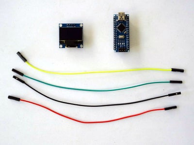
- One Arduino compatible board (I use Arduino Nano, because I have one, but any other will be just fine)
- One I2C SSD1306 OLED Display
- 4 Female-Female jumper wires
Step 2: Connect the SSD1306 OLED Display to Arduino

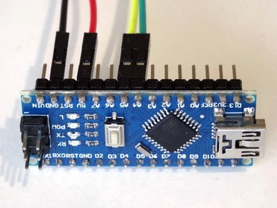
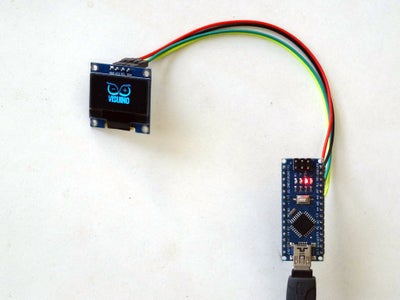
- Connect Female-Female wires - Power(Red wire), Ground(Black wire), SDA(Green wire), and SCL(Yellow wire) to the I2C SSD1306 OLED Display (Picture 1)
- Connect the other end of the Ground(Black wire) to the Ground pin of the Arduino board (Picture 2)
- Connect the other end of the Power(Red wire) to the 5V Power pin of the Arduino board (Picture 2)
- Connect the other end of the SDA wire(Green wire) to SDA/Analog pin 4 of the Arduino Nano board(Picture 2)
- Connect the other end of the SCL wire(Yellow wire) to SCL/Analog pin 5 of the Arduino Nano board(Picture 2)
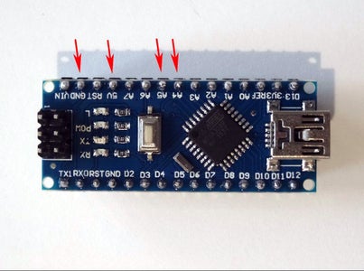
- Picture 3 shows where are the Ground, 5V Power, SDA/Analog pin 4, and SCL/Analog pin 5 pins of the Arduino Nano
Step 3: Start Visuino, and Select the Arduino Board Type

To start programming the Arduino, you will need to have the Arduino IDE installed from here: http://www.arduino.cc/.
Please be aware that there are some critical bugs in Arduino IDE 1.6.6.
Make sure that you install 1.6.7 or higher, otherwise this Instructable will not work!
The Visuino: https://www.visuino.com also needs to be installed.
Step 4: In Visuino: Add and Connect the SSD1306 OLED Display Component
We need to add component to control the OLED Display:
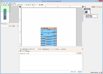
- Type "oled" in the Filter box of the Component Toolbox, then select the "SSD1306 OLED Display (I2C)" component (Picture 1), and drop it in the design area (Picture 2)
- In the Object Inspector, you may need to change the value of the "Address" property of the DisplaySSD13061 component (Picture 2) (See this Instructable to learn how you can scan the I2C bus to find the I2C Address of the Display)
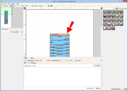
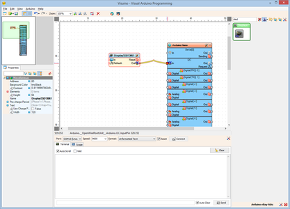
- Connect the "Out" pin of the DisplaySSD13061 component to the "In" pin of the "I2C" channel of the Arduino component (Picture 2)
Step 5: In Visuino: Add Bitmap Element to the Display Component


Next we need to add a Bitmap element to be Displayed:
- Click on the "Tools" button of the DisplaySSD13061 component (Picture 1)
- In the "Elements" editor select the “Draw Bitmap” element, and then click on the "+" button on the left to add a Draw Bitmap Element (Picture 2)
Step 6: In Visuino: Select a Picture for the Bitmap Element


- Select the newly added "Draw Bitmap1" element (Picture 1)
- In the Object Inspector select the "Bitmap" property, and click on the "..." button next to its value (Picture 1)
- In the "Bitmap Editor" click on the "Load..." button (Picture 2)
- In the File Dialog, select an image file (Picture 3)
- If necessary, you can invert the pixels by clicking on the "Invert" button (Pictures 4 and 5)
- Close the "Bitmap Editor" dialog.
Step 7: In Visuino: Set the Properties of the Bitmap Element


- In the Object Inspector, set the value of the "Fill Color" property to "tmcBlack" (Picture 1) - This means that any black pixel in the bitmap will be drawn, and erase what was on the display before. By default the black pixels are considered transparent.
- In the Object Inspector, set the value of the "X" property to "30" (Picture 2)
- In the Object Inspector, set the value of the "Y" property to "14" (Picture 3)
Step 8: In Visuino: Add Pins for the X, and Y Position of the Bitmap Element


To animate the Bitmap movement, we need to control the X and Y properties. To do that we will add pins to them:
- In the Object Inspector select the "X" property (Picture 1)
- Click on the "Pin" button at front of the property (Picture 1)
- From the Drop Down list select the "Integer SinkPin" (Picture 2)
- Do the same for the "Y" property (Picture 3)
- Close the "Elements" dialog (Picture 4)
- You will see the new "X", and "Y" pins added to the "Elements.Draw Bitmap1" element (Picture 4)
Step 9: In Visuino: Add and Configure Integer Sine Generator for the X Movement of the Bitmap


Next we will add Sine generators to control the X, and Y pins that we added, this way moving the Bitmap around the screen:
- Type "sine" in the Filter box of the Component Toolbox, then select the "Sine Integer Generator" component (Picture 1), and drop it in the design area (Picture 2)
- In the Object Inspector, set the value of the "Amplitude" property of the SineIntegerGenerator1 component to "30" (Picture 2)
- In the Object Inspector, set the value of the "Offset" property of the SineIntegerGenerator1 component to "30" (Picture 3)
- In the Object Inspector, set the value of the "Frequency" property of the SineIntegerGenerator1 component to "0.1" (Picture 4)
Step 10: In Visuino: Add and Configure Integer Sine Generator for the Y Movement of the Bitmap


- In the Component Toolbox, again select the "Sine Integer Generator" component (Picture 1), and drop it in the design area (Picture 2)
- In the Object Inspector, set the value of the "Amplitude" property of the SineIntegerGenerator2 component to "14" (Picture 2)
- In the Object Inspector, set the value of the "Offset" property of the SineIntegerGenerator2 component to "14" (Picture 3)
- In the Object Inspector, set the value of the "Frequency" property of the SineIntegerGenerator2 component to "0.2" (Picture 4)
Step 11: In Visuino: Connect the Sine Generators to the Bitmap Element


- Connect the "Out" output pin of the SineIntegerGenerator1 component to the "Clock" input pin of the "Elements.Draw Bitmap1" of the DisplaySSD13061 component (Picture 1) - This will force the bitmap to be drawn every time the generator generates a new value
- Connect the "Out" output pin of the SineIntegerGenerator1 component to the "X" input pin of the "Elements.Draw Bitmap1" of the DisplaySSD13061 component (Picture 2)
- Connect the "Out" output pin of the SineIntegerGenerator2 component to the "Y" input pin of the "Elements.Draw Bitmap1" of the DisplaySSD13061 component (Picture 3)
Step 12: Generate, Compile, and Upload the Arduino Code

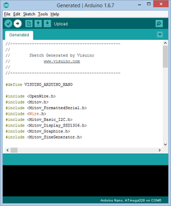
- In Visuino, Press F9 or click on the button shown on Picture 1 to generate the Arduino code, and open the Arduino IDE
- In the Arduino IDE, click on the Upload button, to compile and upload the code (Picture 2)
Step 13: And Play...

Congratulations! You have completed the project.
Picture 1 and the Video show the connected and powered up project. You will see the Bitmap moving around the OLED Display as seen on the Video.
On Picture 2 you can see the complete Visuino diagram.
Also attached is the Visuino project, that I created for this Instructable, and the bitmap with the Visuino logo. You can download and open it in Visuino: https://www.visuino.com


