

Introduction: Arduino Passcode Lock


This Instructable will show you a way to create an addon to many locking mechanisms. It will be capable of unlocking the lock with a few key presses. It can be used on bedroom doors or even house doors. I find that this can be useful for many people for multiple purposes.
*Disclamer: Much of this Instructable is not mine. It is from ibenkos's Instructable at https://www.instructables.com/id/Arduino-door-lock-...*
Step 1: Materials Needed

For this Instructable you will need a variety of things:
Consumables:
- Arduino Board
- 3 Wire Servo
- 4x4 Keypad
- 1/4in plywood
- 1/4 inch bolts and nuts
- Circuit Board
- 2 150 ohm resistors
- 1 Red LED
- 1 Green LED
- Assorted wires
- Solder
- Assorted screws
- 9v power supply
- Heatshrink
- Optional: 3d Printer Filament
Tools:
- Soldering Iron
- Wrench
- Screw Driver
- Band Saw/Scroll Saw
- Drill Press/Hand Drill
- Belt sander/hand sander
- Dremel
- Computer for programming
- Optional: 3D Printer
Step 2: Build Circuit Board

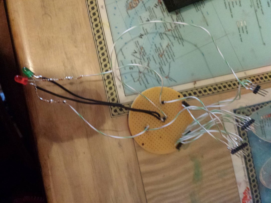
This diagram shows how to wire the board. I would test to make sure the pin output on your keypad is the same before trying this wiring or the keypad.
For the LED's connect the resistors to the positive lead and the negative lead to ground. And according to my math, the resistors should be 150 ohm resistors.
These steps don't necessarily have to be in this order as not much is actually being connected yet.
*This diagram is from ibenkos*
Step 3: Build the Keypad Housing

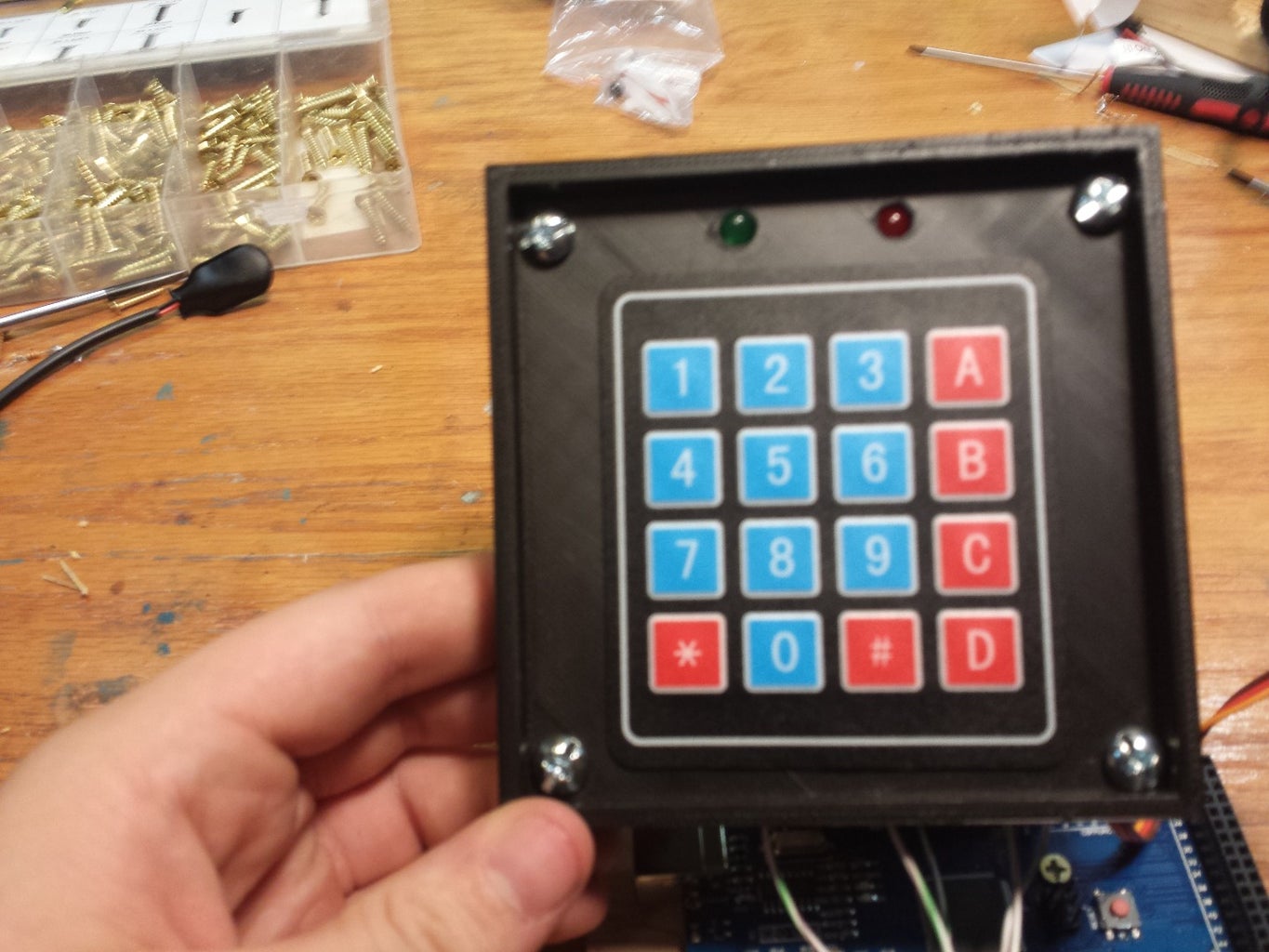
For the keypad housing, I wanted something that was going to be durable and lasting. I decided to make it out of 3d printed plastic to allow it to be weather and water resistant. I felt that it would also look better than wood.
I used Inventor to draw up the design for the housing. I made it bigger than the keypad to allow the LED's and bolts to attach also. I also added a slit that would be behind the keypad to allow me to run the ribbon cable to go through that for aesthetics.
I then 3D printed it using a Cube 3d Printer and it turned out ok, but I needed to drill out the holes for the bolts and LED's as the printer made the holes to small. I also sanded the face of the housing where the keypad is going to adhere to, to allow it to adhere better
Step 4: Build the Arduino and Circuit Board Holder

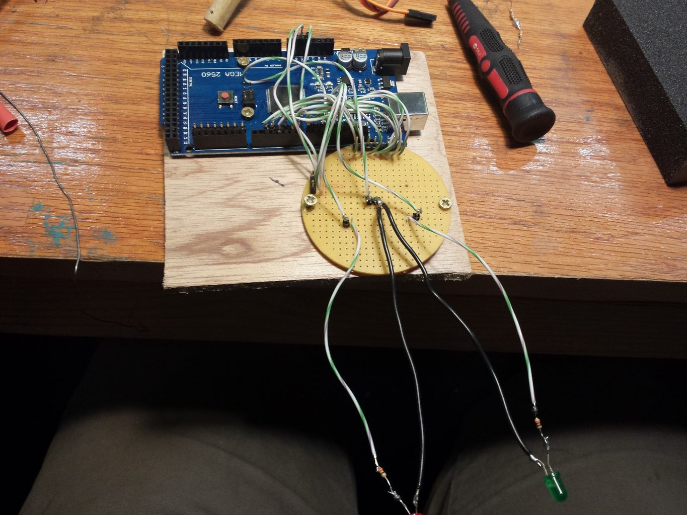
For this you may want to use wood or any other material that you have handy. I used 1/4 inch plywood that I cut using a band saw and scroll saw. I also used a belt and hand sander to get the edges nice and smooth. Arduino board already has holes in it for mounting so you will only need to pre-drill the holes in the wood.
If you also wanted to, to get the circuit board mounted, you can drill out a couple of unused holes on opposite ends of the circuit board to attach the screws to. You can also use hot glue or another adhesive to attach the circuit board if it is too small to drill or you don't want to damage it.
The board that the arduino and circuit board are mounted to can be then mounted to a wall to be out of the way.
Step 5: Build Mechanism for Moving the Latch
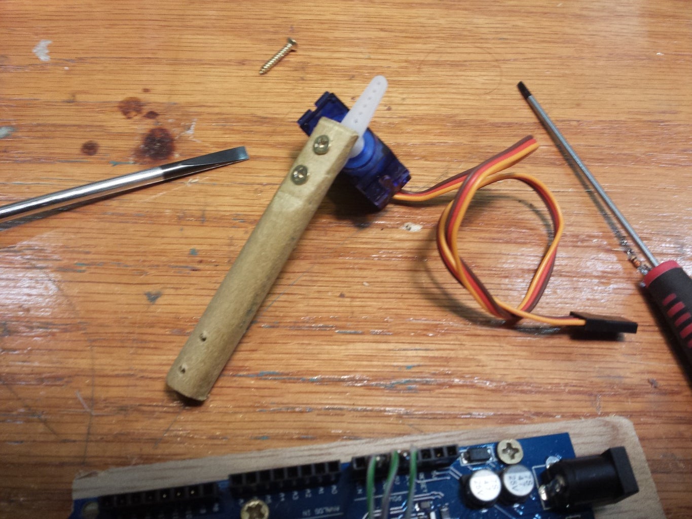

For this step, I used a micro servo and one of the included arms that it came with. I also used a spare wooden dowel that I had lying around. I cut it to be about 2 inches. I also made one of the ends flat for about 3/4 inches because that would be the end that attaches to the servo arm. I also drilled a series of holes in each end. This allowed me to attach the servo to the arm. It will also allow me to attach the arm to whatever lock I wish.
Step 6: Compile the Code
In order to get the program to work properly in the arduino software, you will need to download a few libraries. The needed libraries are:
- password.h
- servo.h
- keypad.h
The code can be changed easily to suit your needs
*this code is from ibenkos and I claim no ownership to it.*
Attachments

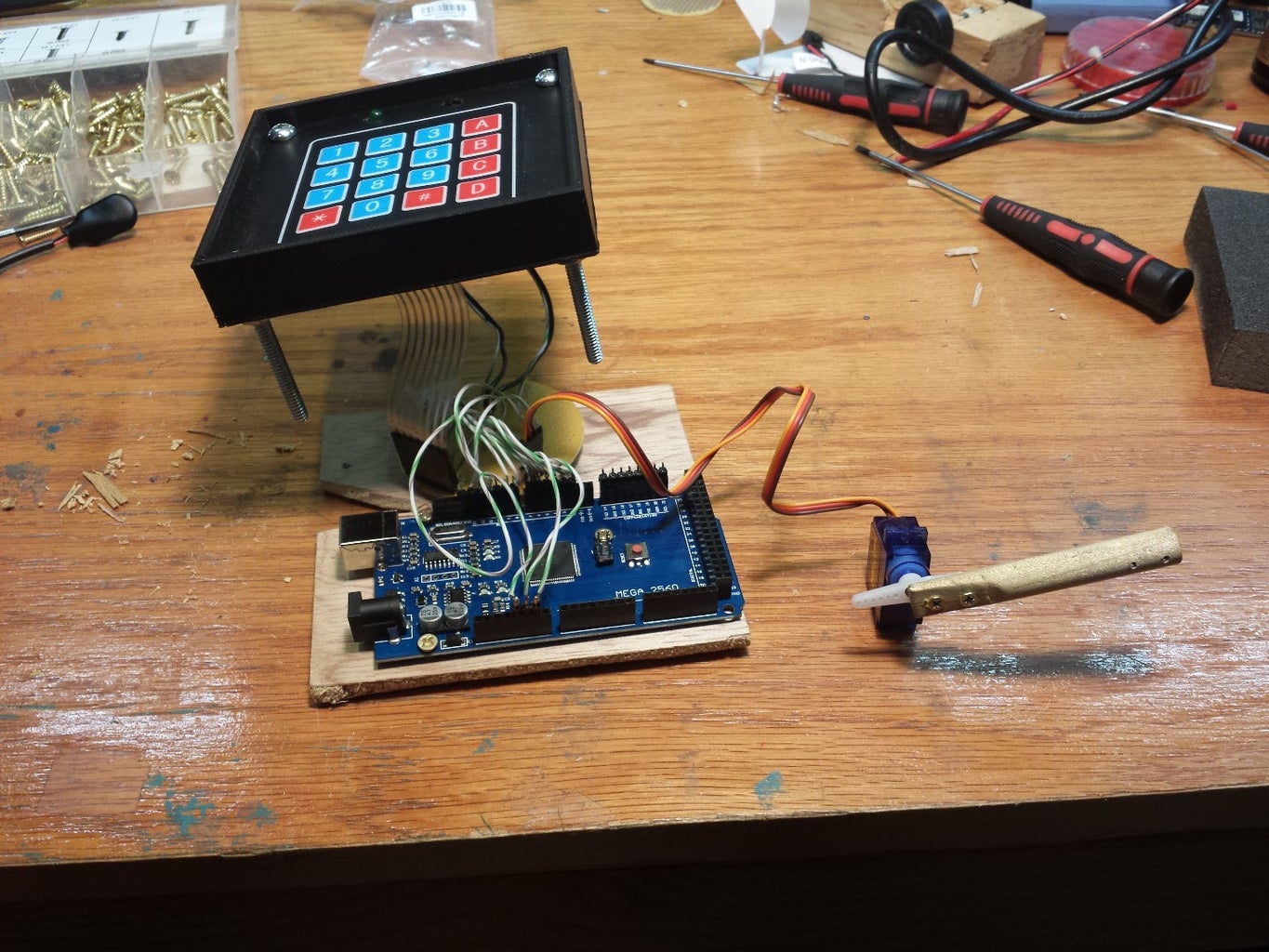
Step 7: Put Everything Together

Once the code is compiled to the arduino you can put everything together.
- Mount the arduino and circuit board on a wall close to the lock
- Mount the servo to the locking mechanism
- Drill through that wall to allow the wires for the keypad and LED's to pass through
- Bolt the keypad holder in place
- Plug in the power supply to the arduino and the wall
- Make sure everything is attached together


