

Introduction: Arduino : Potentio Indicator Uses Led Matrix MAX7219


In the previous tutorial I've made a potentiometer indication using the RGB ring neo pixels led. you can see it in this article "Potentio Indicator Uses RGB Neopixel"
And today I will show the potentiator indicator using the MAX7219 led metric display.
Follow the steps below to make it.
Step 1: Required Components


Required Components :
- Arduino nano
- Potentiometer
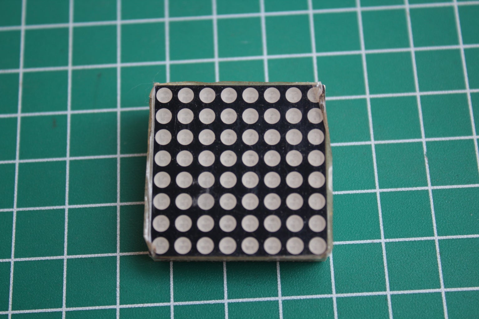
- Max7219 Led Matrix Display
- Jumper Wire
- Project Board
- USB mini
- laptop
Required Library
- LedControl
Step 2: Scheme


To assemble the components see the schematic drawing above, you can also see the information below:
Arduino to Led & potentio
+5V ==> VCC & 3.Potentio
GND ==> GND & 1.Potentio
D6 ==> DataIn
D7 ==> CLK
D8 ==> CS / Load
Step 3: Programming

Use the code below to make ait:
#include "LedControl.h"
/* Now we need a LedControl to work with. ***** These pin numbers will probably not work with your hardware ***** pin 6 is connected to the DataIn pin 7 is connected to the CLK pin 8 is connected to LOAD We have only a single MAX72XX. */
LedControl lc=LedControl(6,7,8,1);
unsigned long delaytime=100;
void setup() { lc.shutdown(0,false); lc.setIntensity(0,8); lc.clearDisplay(0); } void loop() { int val = analogRead(A0); val = map(val, 0, 1023, 0, 8);
if(val == 1) {
lc.setRow(0,0,B10000000); }
if(val == 2) { lc.setRow(0,0,B10000000); lc.setRow(0,1,B10000000); } if(val == 3) {
lc.setRow(0,0,B10000000); lc.setRow(0,1,B10000000); lc.setRow(0,2,B10000000); } if(val == 4) {
lc.setRow(0,0,B10000000); lc.setRow(0,1,B10000000); lc.setRow(0,2,B10000000); lc.setRow(0,3,B10000000); } if(val == 5) {
lc.setRow(0,0,B10000000); lc.setRow(0,1,B10000000); lc.setRow(0,2,B10000000); lc.setRow(0,3,B10000000); lc.setRow(0,4,B10000000); } if(val == 6) { lc.setRow(0,0,B10000000); lc.setRow(0,1,B10000000); lc.setRow(0,2,B10000000); lc.setRow(0,3,B10000000); lc.setRow(0,4,B10000000); lc.setRow(0,5,B10000000); } if(val == 7) { lc.setRow(0,0,B10000000); lc.setRow(0,1,B10000000); lc.setRow(0,2,B10000000); lc.setRow(0,3,B10000000); lc.setRow(0,4,B10000000); lc.setRow(0,5,B10000000); lc.setRow(0,6,B10000000); } if(val == 8) { lc.setRow(0,0,B10000000); lc.setRow(0,1,B10000000); lc.setRow(0,2,B10000000); lc.setRow(0,3,B10000000); lc.setRow(0,4,B10000000); lc.setRow(0,5,B10000000); lc.setRow(0,6,B10000000); lc.setRow(0,7,B10000000); } lc.clearDisplay(0); }
Attachments

Step 4: Result
Once programmed, the results will look like this.
If the potentio is rotated to the right, the live LEDs will increasingly follow the number of turns.
If the pot is turned to the left, the live LED will be less and less following the rotation potency.


