

Introduction: Arduino Powered Rocket Guidance System


This is my first Instructable so bear with me.
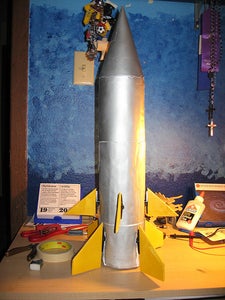
This is an Arduino Powered Rocket Guidance System. I submitted this for the Google Global Science Fair. My science project is at https://sites.google.com/site/arduinorocket/ . It took me three months to design and build the rocket. I could launch the rocket because the rocket was too heavy and I could find enough power to run the servos.
What you will need:
Arduino (Uno or Mega, your choice)
a lot of Jumper wires (like a box of 100 from sparkfun.com )
Memsic 2125 Dual-Axis Accelerometer (you can use whatever sensor you want, i just liked this one)
9v to Barrel Jack Adapter (you can also use, http://www.sparkfun.com/products/10512 )
Solderless Breadboard
Servos (these are pretty expensive, here are some smaller and cheaper ones: http://www.hobbypartz.com/topromisesg9.html )
Step 1: Build the Rocket
The rocket is easy to build once you get the hang of it. The way that I built the rocket is on my blog/website: http://therocketgeek.wordpress.com/my-rockets/phoenix-1/. The building of the rocket isn't that hard, its takes a lot of glue and patience.
Step 2: Servos


The idea was to attach the fins of the rocket to servos. When the accelometer senses that there is movement it tells the Arduino to move certain servos which moves the fins and changes the rocket't trajectory. I originally had only four servos to work the entire rocket. the problem is that the rocket can only move in four axes; this is problem when the rocket moves between axes. To solve this problem I offset another set of fins 45 degrees. This uses eight servos. I bought Common Sense R/C servos from Amazon.com for about $50.
The offset is done by drawing a circle the same diameter as the body tube you made. You then draw a pair of perpendicular bisecting lines at the center of the circle. You then, using a Geometry compass, bisect all four of the angles. You then draw all of the angle bisectors until the line extends outside of the circle. Then line up the first four fins on the bottom of the rocket. Then transfer the lines of the bisectors to the body tube until it is clearly above the lower fins.
Step 3: Servo Plates(disks)


Cut out four disks the same diameter of the body tube. Draw perpendicular bisectors in the center of the disk. Then line up the middle of the servo with the lines. Make sure that just the part that connects to the servo horn sicks outside of the disk. cut a slit to accommodate for the servo brackets. Once servos are lined up and fit in slits, use an Exacto knife to cut smaller slits for zip ties (also known as cable ties). I had to connect two ties together to make a bigger tie. Wrap tie around the servo and the plate and connect the last two ends of the tie until the servo is secure to the disk. Clip off the ends to clean up a bit.
Repeat this process until all servos are secured to the disks. There should be four servos on two disks.
Then cut slits on the two other cardboard disks for zip ties. secure these to the servos as well.
On only one of the servo disks cut four holes in the shape of standard sized Estes Rocket motors (A-C). Roll four note cards in the shape of the rocket engines. Then insert and glue these to the servo plates.
Step 4: Fitting Together


Cut squares on the disks. Pull servo wires out through squares and pull them into the body tube. I straightened paperclips and cut them into sections to fit into the servo plug and onto the breadboard. I connected all of the servos to the breadboard and then connected all of the power lines to the + and - rails on the board. Be sure to know what wire does what! If you don't this won't work. Black means Ground or Gnd. Red or Orange means 5v or whatever your servo requires to move. White or whatever the color is of the last wire is the line in that tells the servo how far to move. The line in wires need to go to the PWM pins on the Arduino. I used 0-7 PWM pins on the Arduino. Then I connected five 9v batteries in series, then taped them together to make a battery pack. Connect the positive end of the battery pack to the + rail on the board. Then connect the negative end of the pack to the - rail on the board as well. The Arduino runs off of a 9v batter connected via the barrel jack on the Arduino board.
Step 5: Sensor


Connect the accelerometer's input wires to two PWM pins. Be sure to read the code to find what pins the accelerometer sends info to. The accelerometer's Gnd and 5v can be run off of the Arduino board itself. After everything is connected, stuff everything into the body tube and put the nose cone on. Then attach the fins to the servos. Upload the code and make sure it works.
Like I said before, this rocket was too heavy and I had electrical problems from the battery pack. Don't used aluminum foil on the batteries for the battery back, the foil gets hot and can catch fire. I would use paper clips or something that can conduct electricity really well.
Step 6: Code
This code might not work, feel free to change it and let me know how you changed it. This is the public's domain.
/*
This scketch is based upon the Memsic 2125 accelerometer read code from http://www.arduino.cc/en/Tutorial/Memsic2125
and the RCServoMotorsControlledWithAccelMeter2
based on the ITP's sample code
http://itp.nyu.edu/physcomp/Labs/Servo
These sketches have been modified and reworked by Chris Barta.
therocketgeek.wordpress.com
This example code is in the public domain.
*/
#include <Servo.h>
Servo myservo;
const int xPin = 11; // X output of the accelerometer
const int yPin = 12; // Y output of the accelerometer
long lastPulse = 0; // Time in milliseconds of the last pulse
int refreshTime = 10; // Time needed in between pulses
int minSensorValue[xPin] = {-180, -180}; // the least value the accelerometer can read
int maxSensorValue[yPin] = {180, 180}; // the greatest value the accelerometer can read
int pulseWidth[xPin][yPin] = { 0, 0 }; // Pulse width for the servo motors
int sensorRange[xPin][yPin] = { maxSensorValue[0] - minSensorValue[0],
maxSensorValue[1] - minSensorValue[1] };
int i = 0;
int phase = 0; // variable to select the servo motor to drive
void setup()
{
myservo.attach(1, 45, 135); // define what pin the servos are on
myservo.attach(2, 45, 135); // the minimum angle
myservo.attach(3, 45, 135); // that can be rotated
myservo.attach(4, 45, 135); // and the maximum angle
myservo.attach(5, 45, 135); // that can be rotated
myservo.attach(6, 45, 135);
myservo.attach(7, 45, 135);
myservo.attach(8, 45, 135);
myservo.write(90); // set servo to mid-point (90 degrees)
pinMode(xPin, INPUT); // set x value from accelerometer as an input
pinMode(yPin, INPUT); // set y value from accelerometer as an input
}
void loop()
{
// variables to read the pulse widths:
int pulseX, pulseY;
// variables to contain the resulting accelerations
int accelerationX, accelerationY;
// read pulse from x- and y-axes:
pulseX = pulseIn(xPin,HIGH);
pulseY = pulseIn(yPin,HIGH);
// convert the pulse width into acceleration
// accelerationX and accelerationY are in milli-g's:
// earth's gravity is 1000 milli-g's, or 1g.
accelerationX = ((pulseX / 10) - 500) * 8;
accelerationY = ((pulseY / 10) - 500) * 8;
// pulse the servo again if the refresh time (20ms) have passed:
if (millis() - lastPulse >= refreshTime) {
if (accelerationX < 0) // if the rocket moves off the X-axis then
{
myservo.attach(1); // the two servos 1,3 will move to oppose the movement
myservo.write(135); //the direction of servo 1
myservo.attach(3); // the two servos are facing each other
myservo.write(45); // so they have to move "opposite" directions
} else if (accelerationX > 0); // if the rocket goes in
(accelerationY > 0); // the x,y direction
{
myservo.attach(5); // then the servos in the uppersection
myservo.write(135); // (5,7) sill counteract the motion in that direction
myservo.attach(7);
myservo.write(45);
}
}else if (accelerationX = 0); //if there is no movement then
(accelerationY = 0); // keep the servos aligned with the rocket
{
myservo.attach(5);
myservo.write(90);
myservo.attach(7);
myservo.write(90);
}
{
if (accelerationX > 0) // same thing only in the other direction
{
myservo.attach(1);
myservo.write(45);
myservo.attach(3);
myservo.write(135);
}else if (accelerationX < 0);
(accelerationY < 0);
{
myservo.attach(5);
myservo.write(45);
myservo.attach(7);
myservo.write(135);
if (accelerationX = 0);
(accelerationY = 0);
{
myservo.attach(5);
myservo.write(90);
myservo.attach(7);
myservo.write(90);
}
}
if (accelerationX = 0); //if there is no movement
{
myservo.attach(1); // then keep the servos aligned with the rocket
myservo.write(90);
myservo.attach(3);
myservo.write(90);
}
}
if (accelerationY < 0)
{
myservo.attach(2);
myservo.write(45);
myservo.attach(4);
myservo.write(135);
}else if (accelerationX > 0);
(accelerationY < 0);
{
myservo.attach(6);
myservo.write(135);
myservo.attach(8);
myservo.write(45);
}
{
if (accelerationX = 0);
(accelerationY = 0);
{
myservo.attach(6);
myservo.write(90);
myservo.attach(8);
myservo.write(90);
}
}
{
if (accelerationY > 0)
{
myservo.attach(2);
myservo.write(135);
myservo.attach(4);
myservo.write(45);
}else if (accelerationX < 0);
(accelerationY > 0);
{
myservo.attach(6);
myservo.write(45);
myservo.attach(135);
myservo.write(135);
}
{
if (accelerationX = 0);
(accelerationY = 0);
{
myservo.attach(6);
myservo.write(90);
myservo.attach(8);
myservo.write(90);
}
}
}
if (accelerationY = 0);
{
myservo.attach(2);
myservo.write(90);
myservo.attach(4);
myservo.write(90);
}
{
delay(100); // this is to delay repeat time so the servos can catch up
}
}
Also, you can go to https://sites.google.com/site/arduinorocket/products-experiment . It is pretty much the same thing except there are indentations.

Participated in the
Microcontroller Contest


