

Introduction: Arduino / Processing Audio Spectrum Analyzer

In this Instructable I am going to show how to make a program in Processing that analyzes sound on your computer and sends data to an Arduino that controls an LED matrix to show the spectrum analysis.
I will be explaining where to get materials, explaining the coding and wiring needed and providing example programs that can be adapted.
I will be using an Arduino Nano and and a 32x16 LED Matrix from Sure Electronics.
Step 1: Required Materials/Software and Where to Get Them

The required materials are:
1) An Arduino(doesn't really matter which version/variant)
2) LED Matrix (for this Instructable, I use a 32x16 bicolor matrix, but any matrix should work)
3) A driver chip if your LED matrix doesn't have them integrated, I will be explaining this in more depth.
Inexpensive LED Matrices: Sure Electronics: http://stores.ebay.com/Sure-Electronics
The display I use: http://www.ebay.com/itm/P4-32X16-RG-Bicolor-LED-3mm-Dot-Matrix-Unit-Board-/350527814626?
Required Software:
1) Arduino IDE (I am using version 1.0) found here: http://arduino.cc/en/Main/Software
2) Processing IDE found here: http://processing.org/download/
Step 2: Wiring

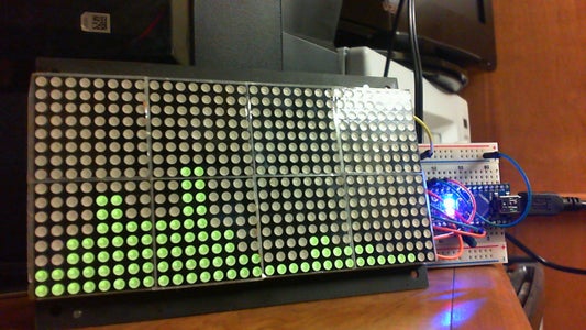
The wiring for this matrix from Sure Electronics, wiring is really simple. The 32x16 bicolor(red, green) uses four HT1632C driver chips integrated into the back of the matrix. The driver chips are what are actually responsible for controlling all the LEDs in the matrix. This particular board is 32x16 'pixels' so to speak. But this is a bicolor matrix so there is actually 1024 LEDs on this board. Now that's a lot of LEDs, but because of the driver chips, we only use 4pins plus +5V and GND to connect the Arduino to the display. This display can also be daisy chained to 3 other displays and still only need 4 pins from the Arduino.
For other matrices, the wiring can range in difficulty. A standard 8x8 matrix needs 16 pins to control it without a driver chip. I will explain about driver chips in the next step.
The 4 pins needed are for the display's Data, CLK, CS, and WR. The connector on the driver chip should be labeled with these or be stated on the chip's datasheet. I have included the wiring for the 32x16 display as shown below. The pins used on the Arduino below can be changed, but the values in the coding must be changed to match.
Step 3: Driver Chips

For a 8x8 matrix, I would suggest getting a MAX7219. This driver chip can control a 8x8 matrix, or 8, 7-Segment displays and only use 4 pins plus a +5V and GND. The MAX7219 can also be daisy chained to another 9 drivers. There are other driver chips available, but the MAX7219 has an Arduino library in existence which makes coding easier for beginners.
Step 4: Coding

This spectrum analyzer is made of two parts: the Processing part that does a Fast Fourier Transformation (FFT) on the stereo mix of the computer and splits the audio into 16 frequency bands and finds their amplitudes and sends this data to the Arduino; then there is the Arduino part that takes the data from the Processing half and lights up the LEDs on the display according to the amplitude of each frequency band.
Processing:
In the processing code, you can define your own frequency band ranges and amplitude ranges that correspond to the # LEDs on the display. The code I am including makes 16 bands that are 2 bars wide each to fill the display's range. This also quicker than sending 32 bands to the Arduino. The more data sent to the Arduino, the more lag the display has.
Arduino:
you need to extract the included libraries into you \Documents\Arduino\libraries folder. If the libraries folder doesn't exist, make one labeled exactly "libraries". The first library ht1632c is for the display like mine. I have also included the ledControl library that is used with the MAX7219.
there are two important lines needed in this program:
#include <ht1632c.h>
ht1632c dotmatrix = ht1632c(PORTD, 7, 6, 4, 5, GEOM_32x16, 2);
the first line tells the compiler to include the ht1632c library. The second then makes a new structure called dotmatrix. anytime you want to call a function from the library, you need to call it with dotmatrix.'whatever'. The numbers and phrases in the parenthesis are: PORTD, DATA_pin, WR_pin, CS_pin, CLK_pin, GEOM_32x16, #ofdisplayschained. Here is where you can change which pins the display is connected to the Arduino. The #displayschained needs to be 2 unless you have more than two displays.
More info about the libraries can be found on the Sources page.
I am including the codes that are being used in my setup. If its not clear, the .pde is for Processing, the .ino is for Arduino. You can run both of the codes as is if you have the same display and setup as I have. You may need to make some changes to accommodate your setup.

Step 5: Sources

Arduino homepage: http://arduino.cc/en/
Processing homepage: http://processing.org/
Sure Electronics: http://stores.ebay.com/Sure-Electronics
More info on the libraries here
ledControl library homepage: http://arduino.cc/playground/Main/LedControl
ht1632c library homepage: http://arduino.cc/playground/Main/HT1632C
Great buyer's source for MAX7219: Jameco.com
or http://www.adafruit.com/products/453

Participated in the
Arduino Challenge


