

Introduction: Arduino RF Sensor Decoder


My previous house came with a pre-installed security system that had door sensors, a motion sensor, and a control panel. Everything was hard wired to a big electronics box in a closet and there were instructions for wiring a landline phone to automatically dial out in case of an alarm. When I tried playing with it I discovered that one of the door sensors was incompletely installed and another was intermittent due to improper alignment. So much for the professional installation touted on the business card of the security company. My solution at the time was to buy a couple of internet security cameras and a cheap wireless security alarm.
Fast forward to today and that wireless alarm is sitting in a box in my basement. After my acquisition of a cheap RF receiver I decided to see if I could decode the messages transmitted by the variety of alarm sensors and remotes that I have. I figured that since they all worked with the cheap alarm box that they must all use the same message format with just a different ID. I soon found out that they are similar only in the general structure of the messages. So the project quickly went from trivial to very interesting.
Step 1: Sensor Modules


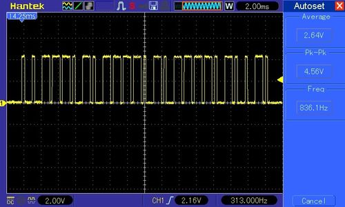
As you can see in the pictures above the transmitters include door open sensors, motion detectors, arming remotes, and a wireless keypad used for programming the alarm box. As it turns out, no two of these devices use the same sync length or bit duration. The only commonality, other than the message length, is the basic format of the bits. Each bit takes up a fixed time period with the difference between a zero and a one being the duty cycle of the high/low portions.
The pretty waveform shown above is NOT what I first received. Because there is so much traffic in the 433-MHz frequency band I had to make sure to activate the sensor just before I set the scope to do a single trigger. Fortunately the sensors put out several copies of the data message when activated and the remotes and keypad continue outputting messages as long as a key is pressed. By using the scope I was able to determine the sync length and the data bit durations for each item. As mentioned previously, the sync times are different and the bit times are different but the message formats all have a low-level sync followed by 24 data bits and one stop bit. That was enough for me to be able to build a generic decoder in software without having to hard code all of the different details for each device.
Step 2: Hardware


I originally built a sensor decoder using a PIC microcontroller and assembly language. I’ve been playing with Arduino variants recently so I thought I would see if I could replicate it. The simple schematic is shown above and there is also a picture of my prototype. All I did was to use three common jumper wires to go from the Arduino Nano to the RF receiver board. Power and a single data line are all that are needed.
If you read my Instructable on the “3-in-1 Time and Weather Display” you will see that I use a common RXB6, 433-MHz receiver. You may be able to get the really cheap receivers to work at the short range needed for this project but I still recommend using a super-heterodyne receiver.
Step 3: Software
The software converts the received bits into displayable ASCII characters. It outputs the value of the sync length, and the lengths of the 1 and 0 bits. Because I already knew the sync lengths and the bit formats, I could have written the software specifically for them. Instead, I decided to see if I could write it to sort out the sync lengths and to automatically figure out the data bits. That should make it easier to modify in case I want to try to detect other formats at some time. It’s important to note that the software doesn’t know if the first bit of a message is a 1 or a 0. It assumes that it is a 1 but, if it figures out that it should have been a zero, it will invert the bits in the completed message before sending it out the serial port.
The times of the sync pulse and the data bits are determined by using the INT0 external interrupt input to trigger an interrupt handler. INT0 can trigger on rising, falling, or both edges, or on a steady low-level. The software gets interrupted on both edges and measures the amount of time that the pulse remains low. That simplifies things because the message start/sync is a low-level pulse and the bits can be determined based on their low-level time.
The interrupt handler first determines if the captured count is long enough to be a start/sync pulse. The various devices I have use sync pulses of 4, 9, 10, and 14 milliseconds. The define statements for the min/max allowed sync values are up front in the software and are currently set for 3 and 16 milliseconds. The bit times also vary between the sensors so the algorithm for decoding bits needs to take that into account. The bit time of the first bit is saved as is the time of a subsequent bit that has a significant difference from the first bit. A direct comparison of subsequent bit times is not possible so a “fudge factor” define (“Variation”) is used. The bit decoding starts by assuming that the first data bit is always recorded as a logic 1. That value is saved and then used to test subsequent bits. If a subsequent data bit count is within the variance window of the saved value then it is also recorded as a logic 1. If it is outside of the variance window of the saved value then it is recorded as a logic 0. If the logic 0 bit time is shorter than the first bit time then a flag is set to tell the software that the bytes need to be inverted before displaying. The only case where this algorithm fails is when the bits in a message are all 0’s. We can accept that limitation because that kind of message is meaningless.
The sensors I am interested in all have a message length of 24 data bits but the software is not limited to that length. There is a buffer for up to seven bytes (more could be added) and defines for the minimum and maximum message length in bytes. The software is set up to collect the bits, convert them into bytes, store them temporarily, and then output them in ASCII format via the serial port. The event that triggers the output of the message is the receipt of a new start/sync pulse.
Attachments

Step 4: Data Logging

The software is set up to output the converted data as ASCII characters via the serial (TX) output of the Arduino. When I made the PIC version I needed to interface to a terminal program on the PC in order to display the data. One advantage of the Arduino IDE is that it has a Serial Monitor function built in. I set the serial port rate to 115.2k and then set the Serial Monitor window to the same rate. The screen shot here shows a typical display with outputs from a variety of sensors that I have. As you can see, the data is sometimes not perfect but you can easily determine what the real value of each sensor should be.
Step 5: Sample Receiver Software

I have included a sample software listing that shows how you can use the collected information to receive a specific set of codes for your application. This example is set up to emulate one of my Etekcity remote outlets. One command turns on the LED built into the Nano (D13) and the other command turns off the LED. If you don't have an LED built into your Arduino, then add the resistor and LED as shown in the diagram. In a real application this function would turn the power on/off for an electrical outlet (using a relay or a triac). The sync times, bit times, and expected data bytes are all defined up front for ease of modification. You can use any of the remaining data lines to turn things on/off, etc. for your specific application. Just add the applicable command code defines and replace the LED on/off logic in “loop” to suit your needs.


