

Introduction: Arduino RGB Color Recognising Flashlight


I am always curious about the sensors that can recognize colors, and I just found an Arduino RGB Color Sensor produced by DFRobot. It will be cool to make a color grab flashlight and put into my backpack.
Arduino RGB Color Grab Flashlight
---Despite thousands of colors, only take one---
Function Description
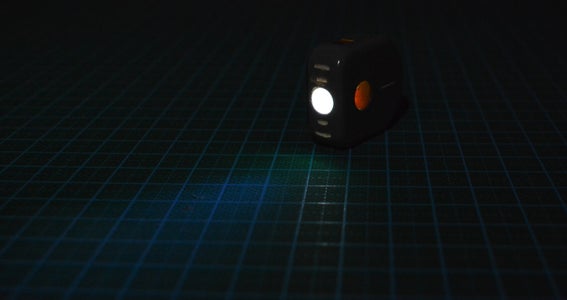
There is only 1 button in the flashlight. Short press the button, open and turn off. Long press it in ON will enter the color grabbing mode and LED is in BLN control. In front of the color you want, short-press the button, the light of the flashlight will be changed accordingly. The color you took will be stored to the EEPROM area which is equals to memory zone, so that the flashlight can memorize the color until you pick up the new one. Short-press the button again, then the flashlight turns off. Let’s store the colorful world to the flashlight now!
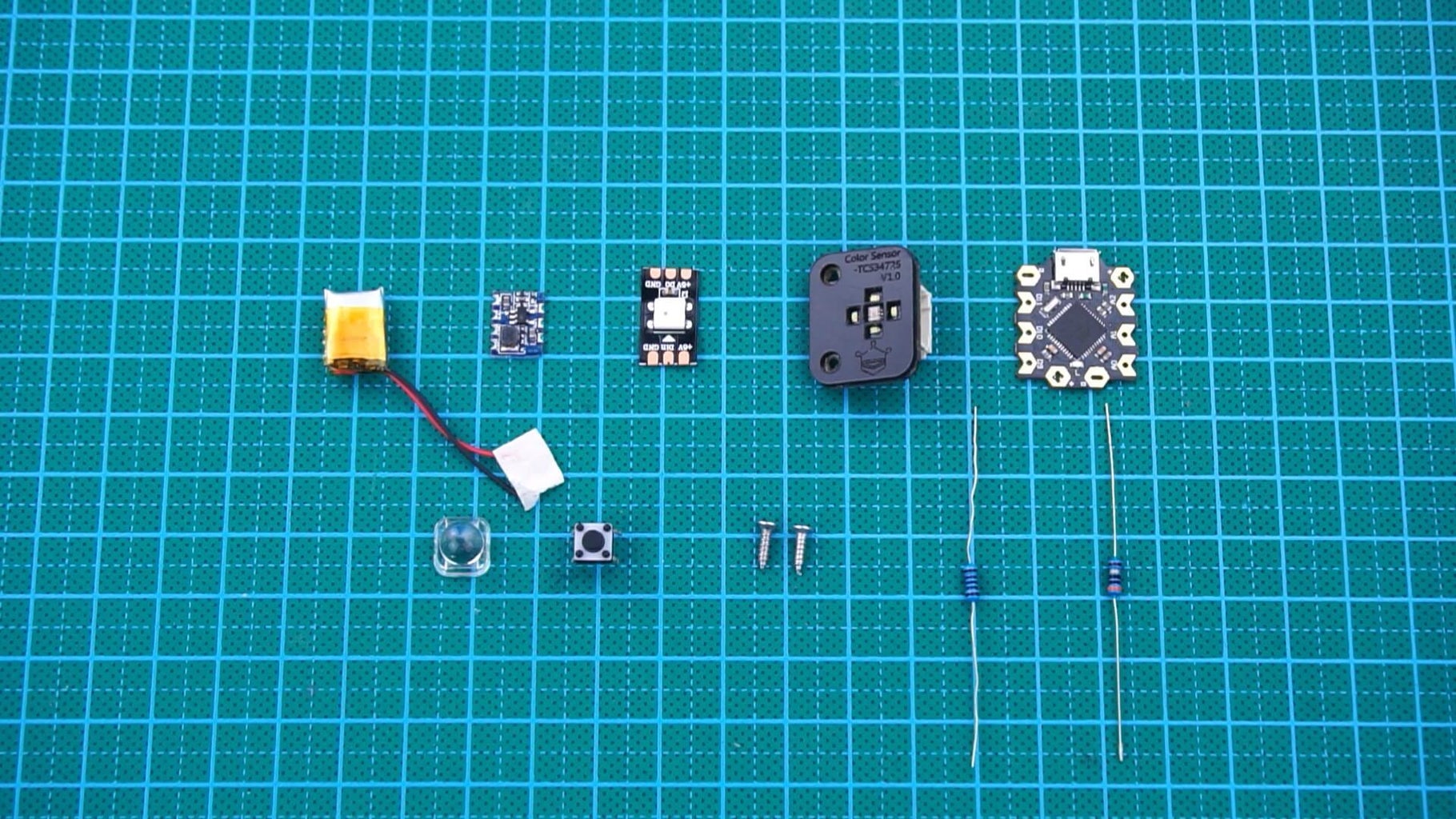
Materials List
1. Gravity: TCS34725 RGB Color Sensor for Arduino
2. Beetle - The Smallest Arduino
3. Digital RGB LED Strip 120 LED-Black
4. Lithium Battery 3.7v 50mah
5. DC-DC Module 5v-4.2v
6. 5050 Spotlight Cover
7. 4 Pin Micro Switch 6*6*5
8. M3.5*10 Self-tapping Screws x2
9. 1kΩ Resistor x1 30Ω Resistor x1
10. 1N4148 Diode x2
11. Acrylic paint Green, Black, Red, White, Grey
12. Spray-paint Black and Grey, and Varnish
Supplies
DFRobot
Step 1: Design Idea
The light of the flashlight is made of 1 RGB and 30-degree spotlight cover. The button is a micro switch. I selected the powerful small Beetle as the main control. Usually, Beetle keeps in sleep, once the button is pressed, Beetle will be awake and light up the RGB LED, or recognize colors. The lithium Battery 3.7v 50mah is adopted as the power supply. In charging, the DC-DC module is used to transfer 5v of Beetle to stable 4.2V to supply the lithium battery.
Step 2: Design the Crust


Step 3: SLA 3D Printing

Step 4: Apply Masking Glue Where Paint Is Not Required


Step 5: Spray Paint to the Main Part of the Crust in Grey

Step 6: Tilt the Masking Glue Applied Before


Step 7: Paint Acrylic to Suitable Positions


Step 8: Remove Unnecessary Acrylic Paint Around With the Sandpaper, and Clean-up Dust

Step 9: Remove Unnecessary Acrylic Paint Around With the Sandpaper, and Clean-up Dust


Step 10: Paint to the Main Part of the Crust in Grey Again, Take Out All Masking Putty and Varnish.


Here the curst work is done.
And the next part is abot Welding Circuits.
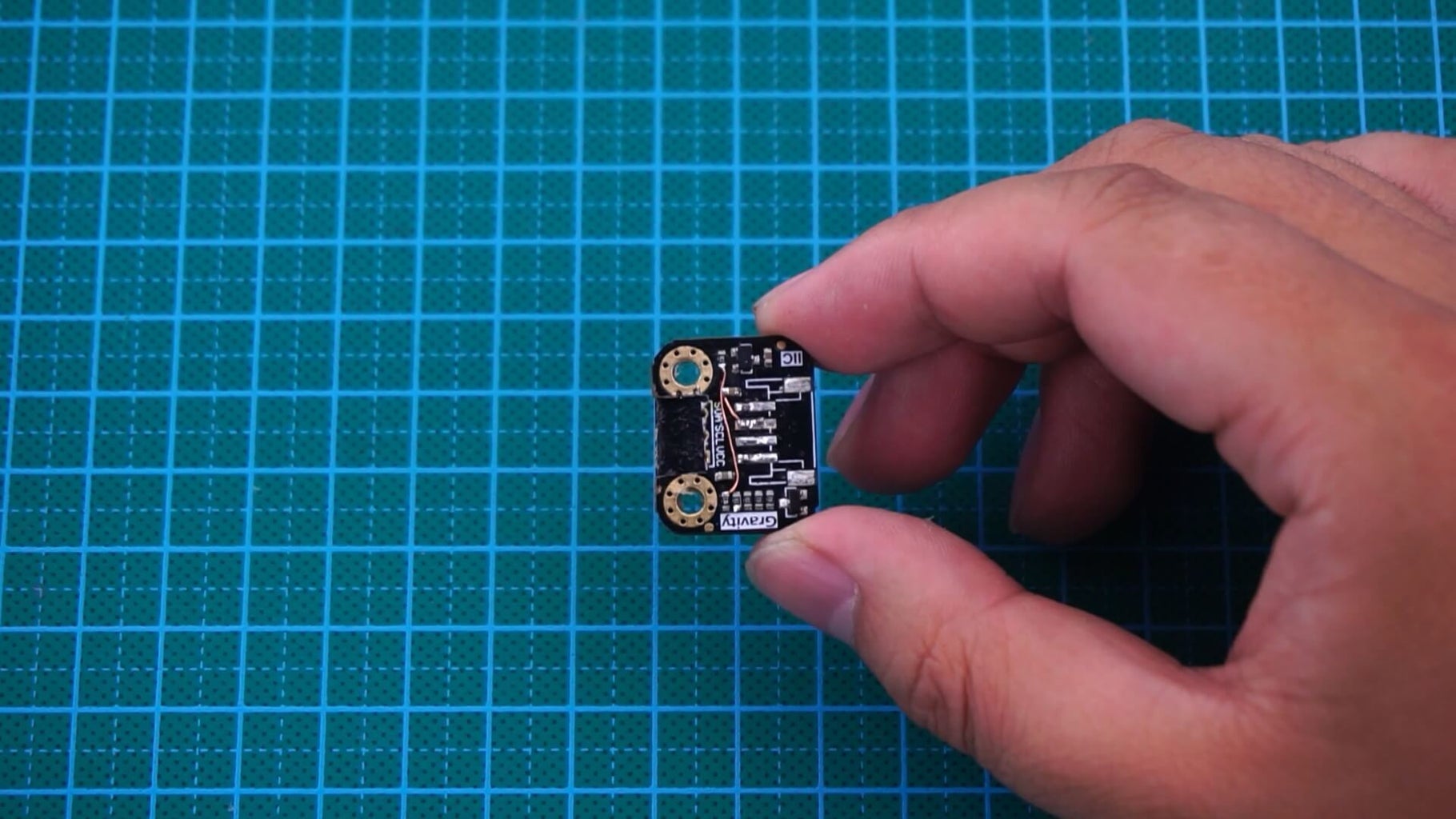
Step 11: Cut Out Beetle and the Color Sensor


The color sensor is made of black acrylic plate and PCB board. Here we just need to cut the PCB part to make it small enough. Well, you can also keep the original size if you do not mind the flashlight size.
Step 12: Short-circuit Pins Shown in the Image

Step 13: Plug the Micro Switch to 4 Holes in the Back Cover, and Flatten Pins to Cling to Its Surface.


Step 14: Weld the Circuit


Please note that the all wielding wires of the color sensor and the micro sensor should go through the square holes in the back cover. Because both of them should be installed in the outside of the back cover.
And the welding work is accomplished!
As follows, we will install it.
Step 15: Fix the Color Sensor to the Back Cover With the Quick-drying Glue Temporarily.


Step 16: Fix the Battery to the Slot in the Back Cover With the Hot-melt Adhesive


Step 17: Fix the Light Cover With the Quick-drying Glue to the Holes Reserved in the Crust


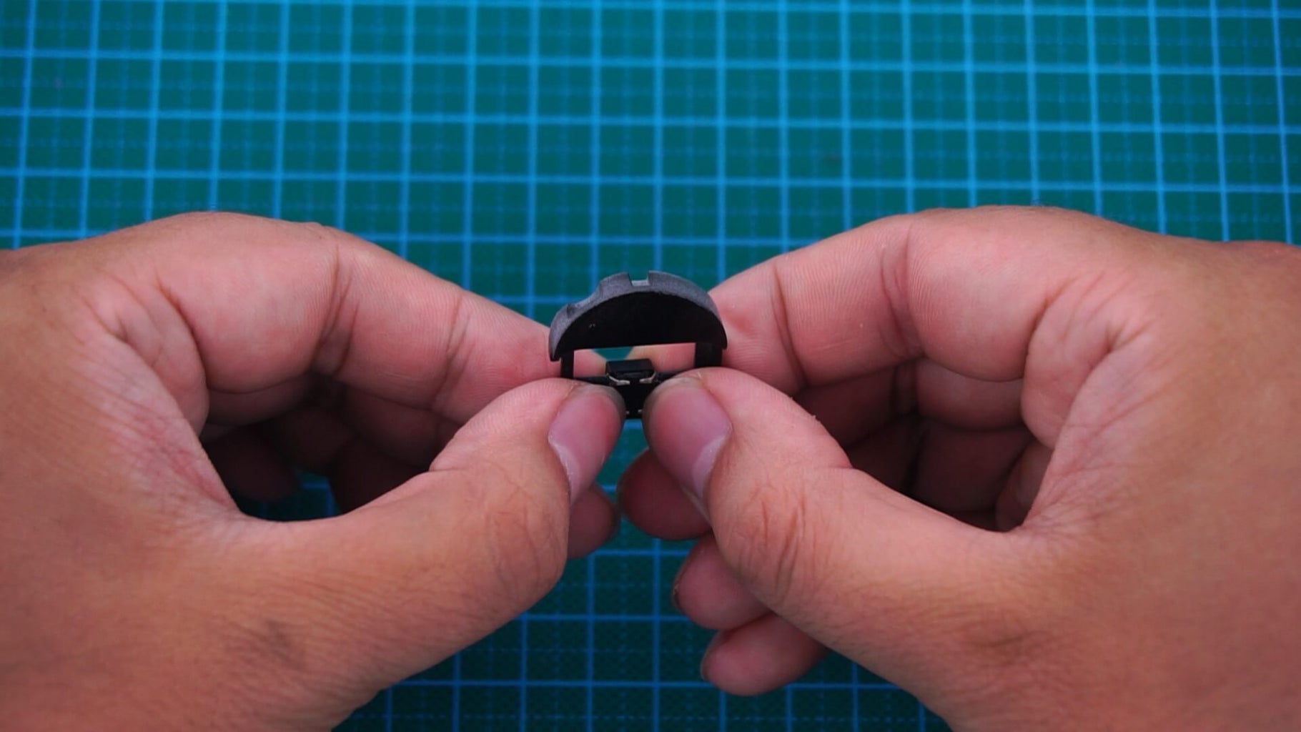
Step 18: Install the Masking Cap

Step 19: Install the Masking Cap


Step 20: Stick the DC-DC Module to the Top Left of the Inner Wall With Hot-melt Adhesive.

Step 21: Put the RGB LED to the Slot in the Back of the Light Cover

Step 22: 8. Put All Wires to the Inner Part of the Crust.

Take off the black acrylic crust, expand the hole size and drill a slope to suit the screw.
Step 23: Install 2 Self-tapping Screws.

Here we finish all work to install.
Step 24: Uploading the Program


Please kindly note that in the end of the program burning, it will not show
“successful loading”, but will remind cannot find the serial port, never mind, it shows that the uploading is done. If you need to upload it again, Beetle should be short circuited, otherwise IDE will not recognize the main control board.
Now we accomplished all works to make a color recognize flashlight.


