

Introduction: Arduino Satellite Array

This instructable was created in fulfillment of the project requirement of the Makecourse at the University of South Florida (www.makecourse.com).
Hello, and welcome to my instructable where I will teach you how to use your Arduino, 5V Stepper Motor and C++ programming skills to replicate my project.
In this Instructable you will find;
1. Descriptions and imags of schematics and dimesnions needed to build parts.
2. A list of materials
3. The code necessary to move the Stepper Motor.
4. A brief lesson on your Arduino and it's electrical components.
Step 1: Schematics and Dimensions - Hull
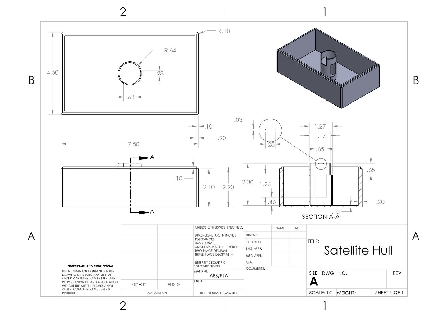
Using AutoDesk, SolidWorks, or another 3D CAD Software; Build the hull that will store your Arduino, breadboard and other electrical components.
If you are confused about dimensions, or believe that they are not compatible with your project then feel free to alter them to best suit your needs.
Special Note: The tower like structure in the center is designed to house and secure your Stepper Motor in place so that it will turn your dish.
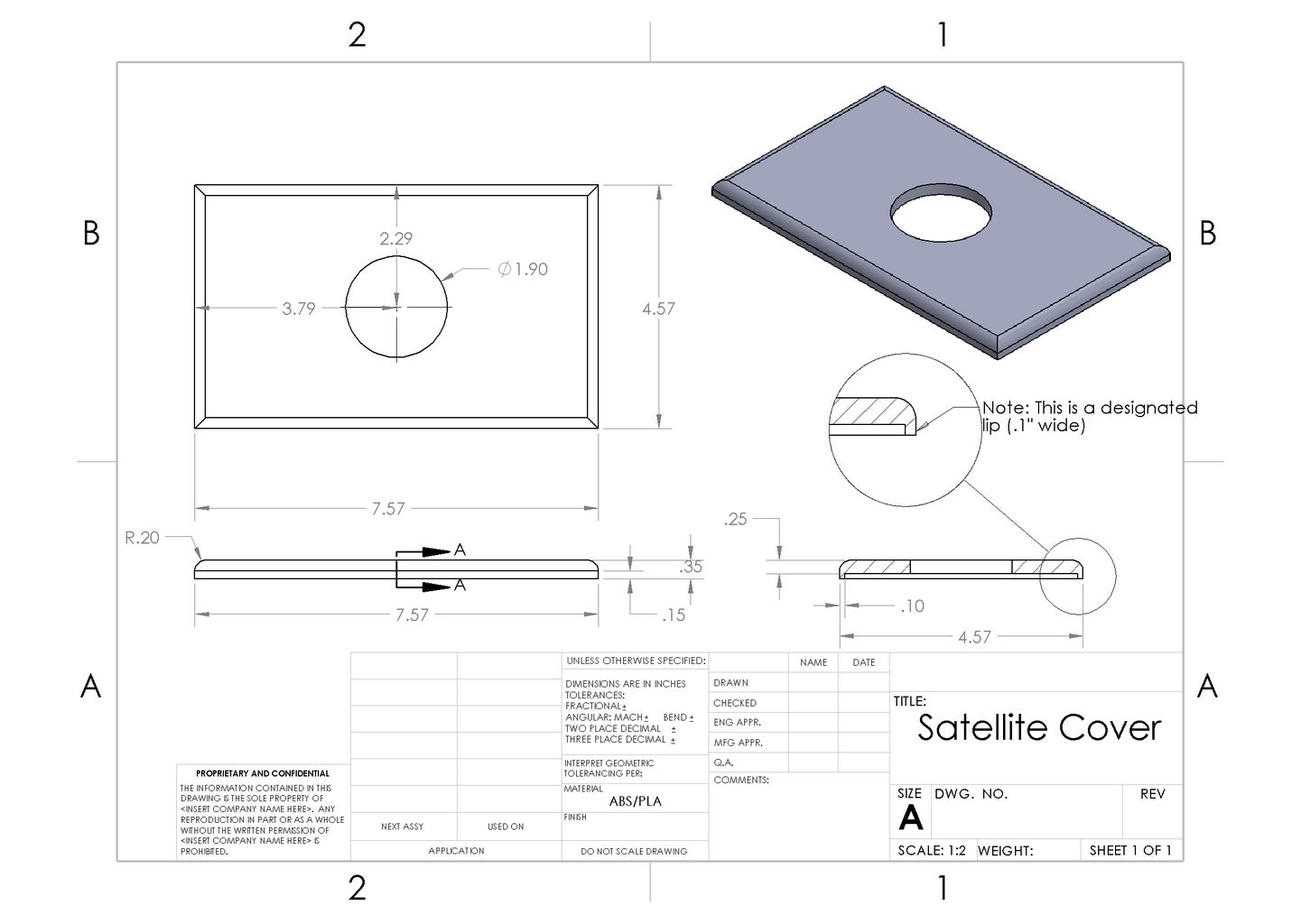
Step 2: Schematics and Dimensions - Base Cover

Using AutoDesk, SolidWorks, or another 3D CAD Software; Build the base cover that will cover the central hole on the Hull.
If you are confused about dimensions, or believe that they are not compatible with your project then feel free to alter them to best suit your needs.
Special Note: The two prong-like teeth on the Base Cover is designed to secure it in place and deter spinning rotation
Step 3: Schematics and Dimensions - Hull Cover
Using AutoDesk, SolidWorks, or another 3D CAD Software; Build the Hull Cover that will enclose your Ardunio and electronics.
If you are confused about dimensions, or believe that they are not compatible with your project then feel free to alter them to best suit your needs.
Special Note: Be sure to see the note about the lip. This lip is needed to secure the hull cover using no screws or other types of hardware.
Step 4: Schematics and Dimensions - Satellite Dish
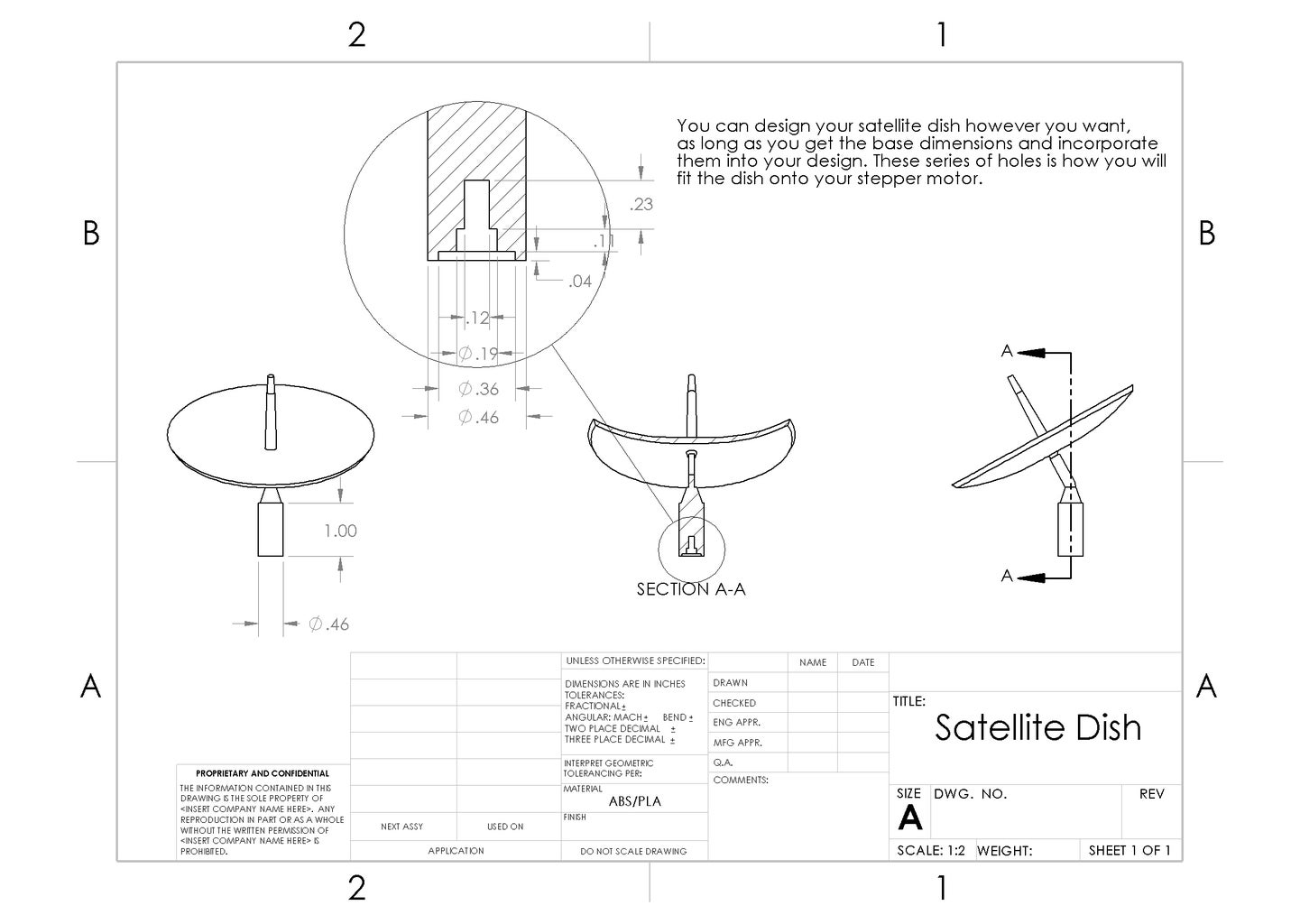
Using AutoDesk, SolidWorks, or another 3D CAD Software; Build the base cover that will cover the central hole on the Hull.
If you are confused about dimensions, or believe that they are not compatible with your project then feel free to alter them to best suit your needs.
Special Note: As long as you build the connector piece with the correct dimensions, then you can design your dish however you like.
Step 5: List of Materials
The following is a complete list of materials needed to replicate the project;
- One 9V Alkaline battery
- One Arduino Uno board
- One breadboard, preferably
- 15 to 20 male-male connnector wires
- 6 female-female connector wires
- Stepper Motor (28BYJ-48 5V DC)
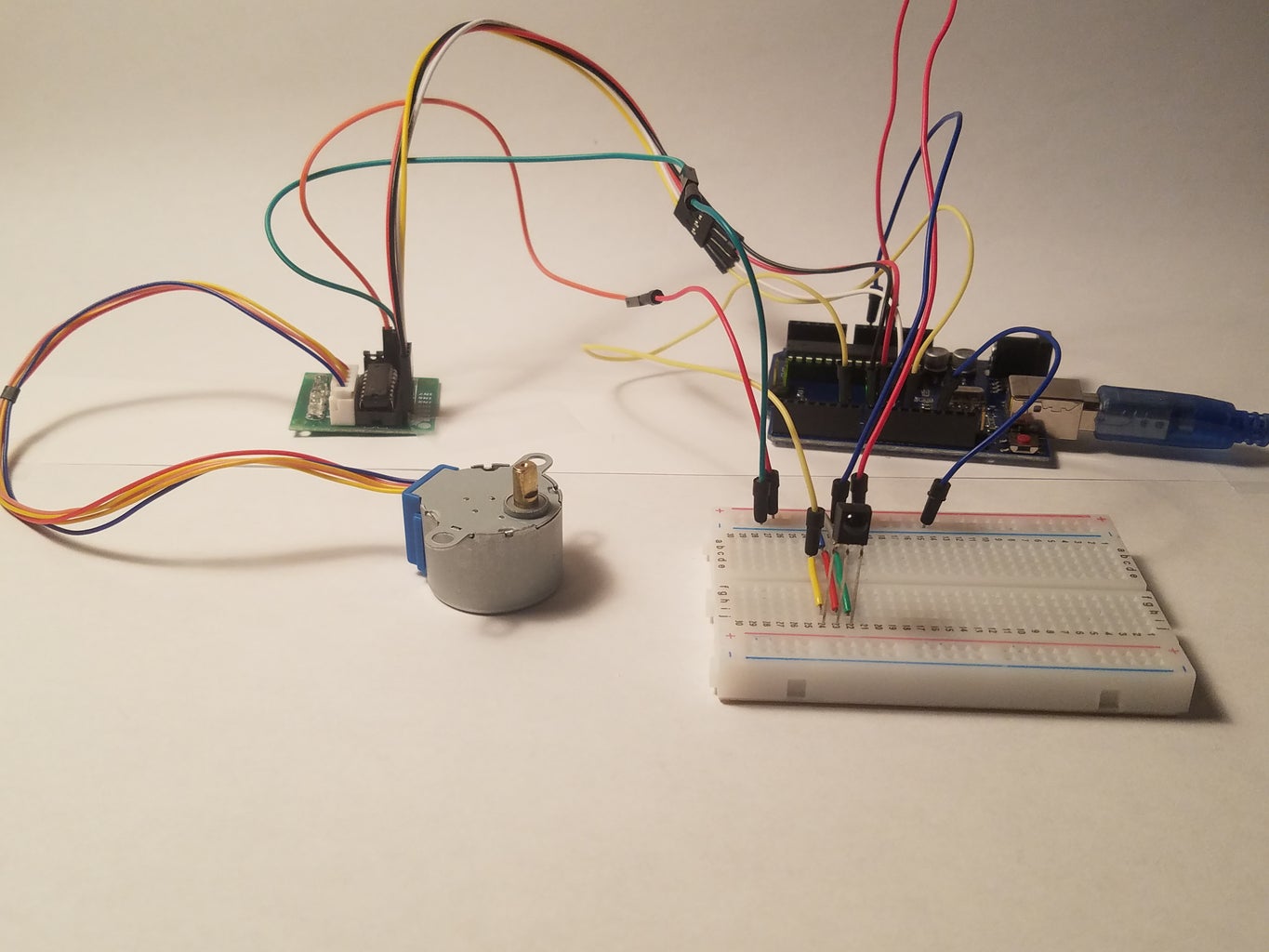
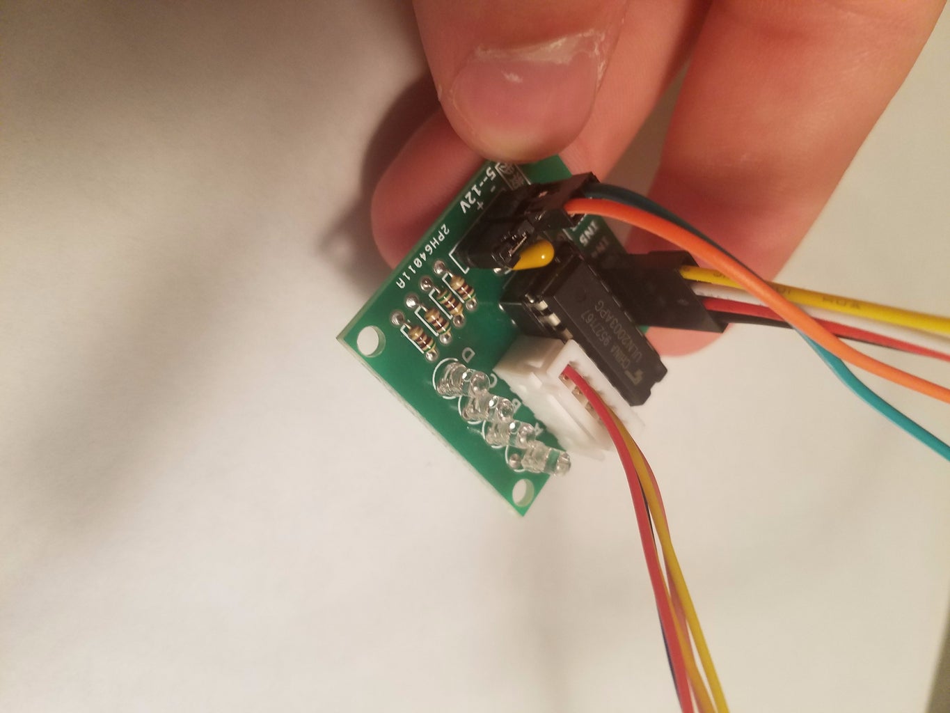
- Stepper Circuit Board (connects between Stepper Motor and Arduino, see pictures)
- Car MP3 Infrared remote
- One three-prong IR Sensor/Receiver
Step 6: The Sketch

In order for this project to work, and make coding easier for you; You must inlcude both the "Stepper.h" and "IRremote.h" files to link and refer your sketch to these components. If you need to, conduct an IR remote test to find your remote codes. Use this link to Makecourse.com to understand more about your IR remote and sensors,
http://makecourse.weebly.com/week9segment1.html
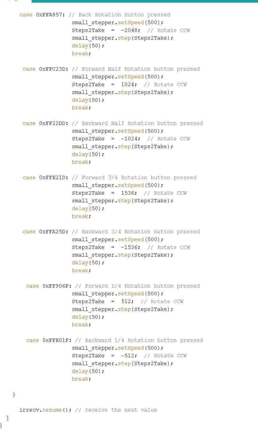
Look at the jpeg (two parts) for the Arduino sketch, and feel free to use the .ino file below.
Attachments

Step 7: A Brief Lesson

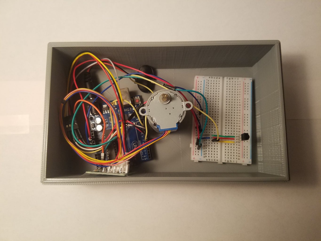
- Plug in your 9V battery and use two male-male connecting wires to draw power to your breadboard. Use the GND pin for your ground and the Vin pin for your positive. Then plug these two wires from your Arduino into the appropriate power rails on your breadboard.
- Place your IR Sensor/Receiver (S/R) on the breaboard. Your IR S/R needs to be connected to both the positive and negative power rail along your breadboard, adjacent or close to your main power cords. The final connection will be for the receving function; Using another male-male connecting wire, connect from your breadboard directly to the corresponding numerical pin you want to be designated as the receiving pin. In my sketch, I used pin 6 but you can use whichever one you want as long as you change the sketch accoring to that.
- For the Stepper Circuit Board, gather 4 female-female connectors and 4 male-male connectors and join these together (should look like 4 male-female total wires). Use the female end of these wires and attach them to the pins labeled "IN 1", "IN 2", "IN 3" and "IN4". Now use the male ends to plug into 8, 9, 10 and 11 pins on your Arduino board. Again, they can be any number as long as you change the coding to appease that.
- There are a series of 5 wires coming from the Stepper Motor itself and have a special connecting end. Connect this to the Stepper Circuit Board (should slide right in).
- For powering the Stepper Circuit Board, use 2 male-male wires and 2 female-female wires. Join these together for 2 total wires (like you did in Step 3). On the Stepper Circuit Board, attach the female ends to the + and - prongs, and keep track of which one is which. Now plug the male ends into the breadboard into the power rails affected by the 9V battery wires (either adjacent or in the same section). The + wire should be in the positive rail and the - wire should be in the negative rail.
- Your setup is complete!
By using the case function, we can customize the severity of rotation and even the direction of our dish. Our job is made much easier by using the Stepper.h file because we can edit the code that it is referencing to in order to change things such as speed and "Steps2Take" (degrees of rotation, 360 degrees = 2048).
Here is a glimpse on the sequencing behind the project.
- The Car MP3 remote sends a coded hex signal to the IR sensor
- The IR sensor receives this code and delivers it to its corresponding receving pin on the Arduino
- Once recognizing the code is responsible for an action, the Arduino sends a series of electrical signals (distributed throughout 4 pins) to the Stepper Motor
- The Stepper Motor completes a specific action (tailored to the coding) given the specific IR signal received from the remote.
Here is the link to my YouTube video below that contains a block diagram and the final product in action!


