

Introduction: Arduino Spectrum Analyzer on a 10x10 RGB LED-Matrix
In this Instructables I am going to show you how to create a spectrum analyzer powered by an Arduino nano. Please watch my video first to get a rough explaination on how to build it.
A spectrum analyzer basically analyzes the intensity of different frequencies in a song. To display those values we are going to use a 10x10 RGB LED-Matrix. Every time one of the columns reaches the top of the matrix the hue value of the colors increases and the matrix looks different.
Step 1: Building the Matrix


To make this awesome spectrum analyzer I first had to build the RGB LED-Matrix. To accomplish this task I have followed the Tutorial of GreatScott on YouTube. He did an awesome job in explaining how to build such a matrix. Just follow the video step by step or use his Instructables as an instruction and then come back and follow the next steps.
Important note: make sure your LEDs are connected as shown in the diagram above. Otherwise my sketch won't work flawless with your matrix.
Step 2: Additional Parts


To convert your Matrix into a spectrum analyzer you need the following additional components:
- 2x 3.5mm headphone sockets
- 2x 1.8kOhm resistors
- 1x 4.7kOhm resistor
- some flexible wire
First of all I had to include the two headphone sockets to the matrix. We use them to loop the audio signal through the matrix to analyze it. We basically connect our audio source (e.g. a smartphone) to one of them and a speaker to the other one. I just drilled two holes according to the diameter of my sockets and glued them in place with two component adhesive.
In the next step you will see why we need those resistors.
Step 3: Connecting the Components

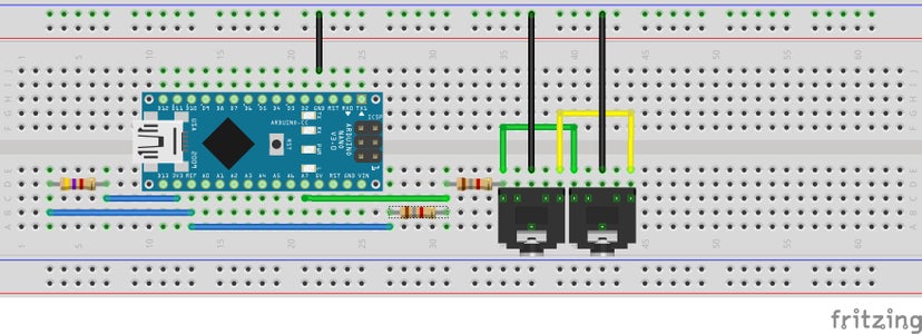

First of all, I have connected 3.3V to the AREF pin of the Arduino through a 4.7kOhm resistor. This is to get a better resolution of the sampled values of the audio signal since they normally reach a maximum of only 1V Peak-to-peak. The reason why we get a better resolution is that the 1024 values of the ADC are now not longer mapped to 0-5V but to 0-2.88V (2.88V because of the 4.7kOhm resistor). To understand why we used a 4.7kOhm resistor and how I have calculated those 2.88V have a look at the analog reference article on the Arduino website.
But there is one problem if you want to analyze an audio signal with an Arduino. The signal is mirrored around 0V. Therefore we get both positive and negative voltage peeks. And because Arduinos can't handle negative voltages we have to get rid of them and create an offset.
As you can see in the schematic above I used a voltage divider with two 1.8kOhm resistors to solve this problem. Since they have both the same resistance the signal now alters around 1.44V (2.88V/2) and we got rid of those negative voltages. To make life easier you can solder the resistors directly to the pins of your Arduino nano.
Lastly I connected the two audio jacks. I simply connected both right and both left channels to each other. I then soldered both GND pins together and connected them to the GND wire of the matrix. Which of the two channels you then connect to the Arduinos A7 Pin / voltage divider doesn't really matter.
Step 4: Programming
To program the built in Arduino nano you first of all have to download both the FastLED and the FFT library. Make sure you have exactly these versions of the libraries listed below otherwise the sketch may not work. Also check if you use at least Arduino IDE 1.6.8 or higher. After you have included both libraries into your Arduino IDE you have to open the "SpectrumAnalyzer" sketch.
Now change the data pin of your LEDs, upload it to your Arduino, connect an audio source and speakers and it is done!
Hope I could help you with this Instructables. If you have any questions feel free to ask them in the comments section below.


Participated in the
First Time Authors Contest 2016

Participated in the
Make it Glow Contest 2016


