

Introduction: Arduino Starter Kit 2: Use Buttons for LED Control


Hello this is Marginally Clever Robots who makes lots of awesome robots. Here is our third tutorial for our Arduino Starter Kit where you can find all the parts you will need for this tutorial.
Check out our previous tutorials here:
Arduino Starter Kit 0: Introduction to Arduino UNO
Arduino Starter Kit 1: First circuit and program to control an LED
In this tutorial, you will learn how to use buttons with Arduino and how to write more complicated program to control multiple LEDs.
Step 1: The Easy Way


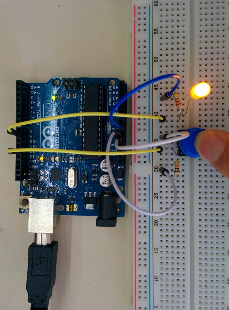
This step will show you how a button works and you don't need to write any program in this step, while you still need to power your Arduino board via USB or any other power sources.
As shown in the picture, the button has four pins. The red connection is ALWAYS there, while the purple connection is established ONLY when you push the button.
Connect the circuits as shown in the figure. Note that the short pin of the LED is always connected to the ground side and the long pin is always connected to the high level voltage side.
Push the button to light up the LED.
Step 2: Program the Button Reading

Modify your circuit. The basic idea is that we use one of the digital pins (pin 12 here) to read signal from button so that the LED can be controlled in the way we want.
Upload the code to your Arduino. When you push the button the light turns on. When you move away your finger, the light turns off.
int ledPin = 9;   // LED connected to digital pin 9<br>int inPin = 12;   // pushbutton connected to digital pin 12
int val = 0;     // variable to store the read value
// the setup function runs once when you press reset or power the board
void setup() {
  // initialize digital pin 13 as an output.
  pinMode(ledPin, OUTPUT);
  pinMode(inPin, INPUT);
}
// the loop function runs over and over again forever
void loop() {
val = digitalRead(inPin);
if(val == 1){ // When you push the button, the reading is 1
digitalWrite(9, HIGH); // turn the LED on (HIGH is the voltage level)
}
else{ // When you not push the button, the reading is 0, not 1
digitalWrite(9, LOW);
}
}The digitalRead() tells us which voltage level is the pin connected to. It can be either HIGH (which is 1) or LOW (which is 0).
When the reading pin (pin 12 here) is not connected to anything, the reading result is random, either 0 or 1. While what we want is to make it 0 when not pushed and 1 when pushed. The way to do it is use a pull down resistor. Basically a 10k Ohm resistor connecting to the reading pin and the GND (ground) on Arduino. The reading pin is also connected to one side of the button, while the other side of the button is connected to the 5V on Arduino.
We use if else logic in the code to decide whether the LED should turn on. Basically on when the reading is HIGH, aka the button is pushed, the LED will turn on.
Step 3: Button Control Multiple LEDs


This step shows you how to turn on and off LEDs one by one.
When you push the button everytime one LED will be turned off and the next one would be turned on. After the third LED is turned off, the first LED will be turned on again.
Here is the code:int ledPin1 = 9; // LED connected to digital pin 9
int ledPin2 = 8; int ledPin3 = 7; int inPin = 12; // pushbutton connected to digital pin 12 int val = 0; // variable to store the read value int index = -1; // to indicate which led should be turned on // the setup function runs once when you press reset or power the board void setup() { // initialize digital pin 13 as an output. pinMode(ledPin1, OUTPUT); pinMode(ledPin2, OUTPUT); pinMode(ledPin3, OUTPUT); pinMode(inPin, INPUT); }// the loop function runs over and over again forever void loop() { val = digitalRead(inPin); if(val == 1){ // the button is pushed // turn off the LED which is on now if(index != -1){ // if index is not the initial value switch (index){ case 0: digitalWrite(ledPin1, LOW); // turn the LED off (LOW is the voltage level) delay(200); break; case 1: digitalWrite(ledPin2, LOW); delay(200); break; case 2: digitalWrite(ledPin3, LOW); delay(200); break; } } // turn on the next LED index ++; index = index % 3; switch (index){ case 0: digitalWrite(ledPin1, HIGH); // turn the LED on (HIGH is the voltage level) delay(200); break; case 1: digitalWrite(ledPin2, HIGH); delay(200); break; case 2: digitalWrite(ledPin3, HIGH); delay(200); break; } } }
Switch functions similarly as if, it's like using if and else if when you have multiple conditions. Check out more information about switch here in the bottom: http://www.cplusplus.com/doc/tutorial/control/
% is the mod operation, for example:
0%3 =0
1%3 =1
2%3 =2
3%3 =0
4%3 =1
5%3 =2
Thank you for watching. This is Marginally Clever Robots Arduino tutorial series for our Arduino Starter Kit.
Our next tutorial would be about how to read from potentiometer and use it to control the brightness of LEDs.


