

Introduction: Arduino Terminal


So I recently got my Seeed Studio Ethernet Shield working, and I thought the SD card function was pretty cool. I wanted a way to display information from it. So I loaded up some demo programs, and decided to go a little bit farther with it. I wanted to make a sort of terminal, with keyboard input and a type of video output.
I did some tinkering with some PS/2 connectors, along with some waiting for a PS/2 keyboard to arrive from Amazon, and I got that working. I then started to think about the output. I had used the TVout library before, so I tried to hook that up. The two libraries, the PS/2 and TVout libraries, wouldn't work together. Like, at all. This I found out is because some sort of internal clock (I may have this information wrong) it uses, and when interrupted with almost any other library won't work, either the TVout or the other library, sometimes neither one. I tried doing things like two Arduino's with IR communication, the Wire library, everything. Nothing would work.
After about a week of testing and failing, I remembered I still had a Seeed Studio 2.8" TFT Touch Shield that I got when everything was 80 - 90% off at Radio Shack (From when they were closing my local store). I hooked that up, wrote a bit of code, and everything worked perfectly. I whipped out my camera, and started building.
Now what I have is a fully functioning terminal with keyboard capabilities, and a full color display. Now, I want to show you how to make it, without failing on every other thing you do.
Step 1: Materials

^ Click image to fix bug with image
If you already have the shields and the Arduino mega, this should be very cheap, maybe free!
The materials you will need are:
- Any working PS/2 keyboard (A PS/2 to USB connector will NOT work)
- About 6 inches of pool noodle
- Resealable plastic refrigerated meat container dimensions: about 4 1/2" x 6 1/2" x 2 1/4" (You can use any container that will fit everything)
- A few inches of PCB with copper dots
- 2x 9v Battery connectors
- 2x 9v printers
- DC power jack plug
- Male breakaway connectors
- 22 gauge, solid core copper wire (I just used speaker wire)
- A small toggle switch
- A PS/2 Female connector with wires exposed
- Arduino MEGA
- Seeed Studio v1.0 2.8" TFT Touch Shield (For Arduino)
- Seeed Studio v2.0 Ethernet Shield (For Arduino)
Tools:
- Soldering iron (With solder)
- Hot glue gun (With hot glue)
- Wire strippers
- X-Acto Knife
- (Optional) Pliers
Step 2: Making the PCB - Headers
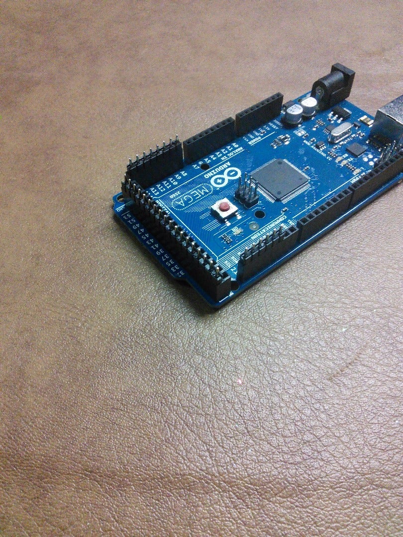

First thing we want to do is make the PCB to go on the back of the Arduino MEGA, so you can easily take all of the external wires in a shield - like format.
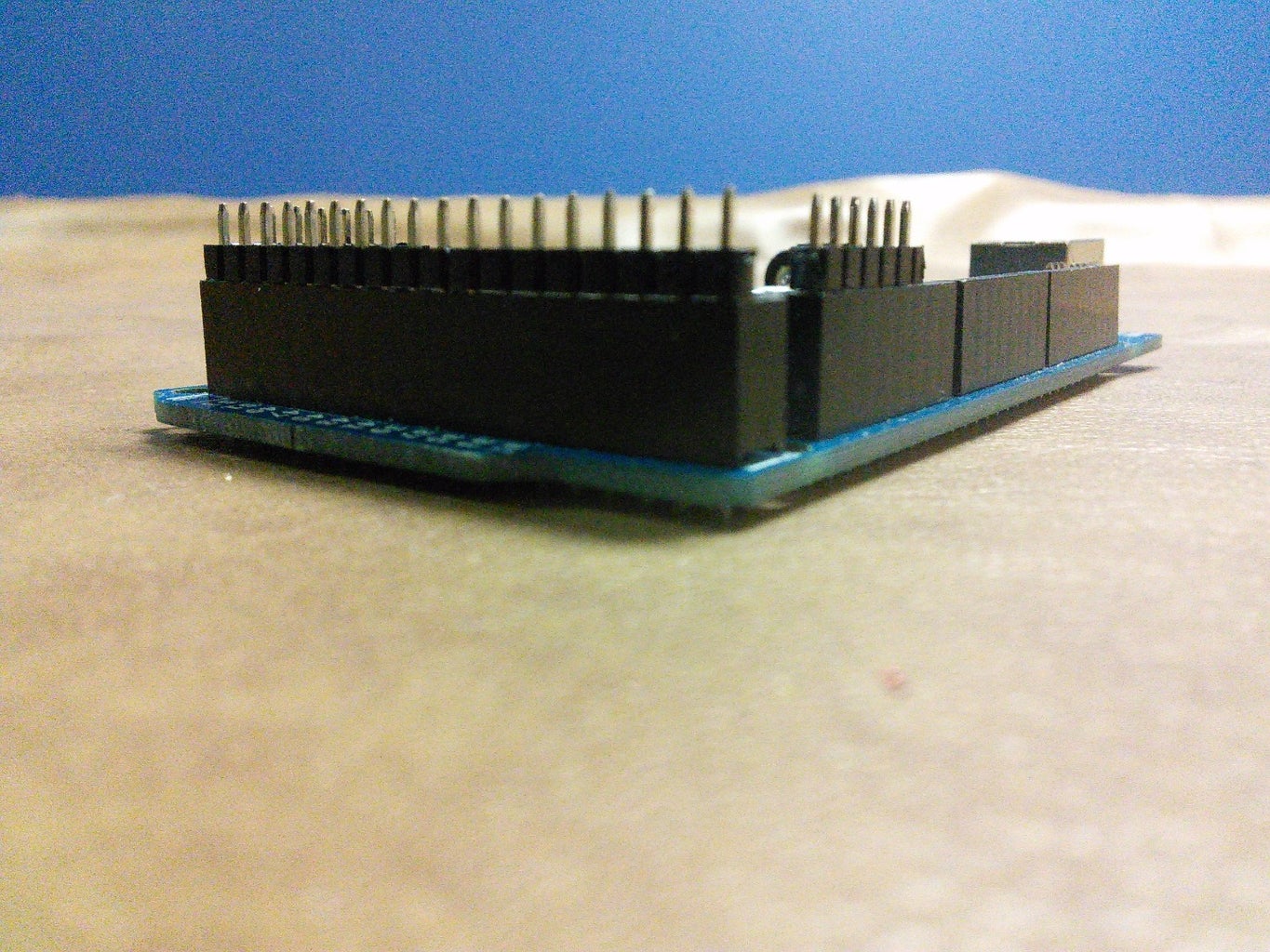
You first will need to cut your male headers. You will want to cut them in sets of 6, 8, and 18, which you can do with scissors or an X-Acto knife.
The set of 6 goes on the Digital 16 - 21
The set of 8 goes on the Analog 8 - 15 pins.
The set of 18 goes on the back row of the two - wide Digital 22 - 53 pins.
Make sure everything fits and is the right size, and you're ready to cut the PCB!
Step 3: Making the PCB - Cutting the PCB


If you have never cut PCB before (Like me) you will know there are many ways to do so, by a quick search on google. Being I was too lazy to add more tools to the parts/materials picture, I decided to use an X-Acto knife.
What I found is best to do is first make a small outline of where you want to cut on the holes, which the inside, untouched area should be 10 x 20 copper dots. Then, proceed to tilt your X-Acto knife vertically, and place it in one of the copper dot holes on the very edge (Not one of the inside holes) and spin your X-Acto knife until after an awful screeching noise, the hole it enlarged is a little bigger than the copper that was once there, so it should be not visible anymore. Repeat this for all holes so, again, the untouched holes make a 10 x 20 copper dot rectangle.
After, grab your X-Acto knife and break the small barriers (Or snap if you feel risky) in between the small holes, so you now have a standalone piece of PCB!
Step 4: Making the PCB - Soldering
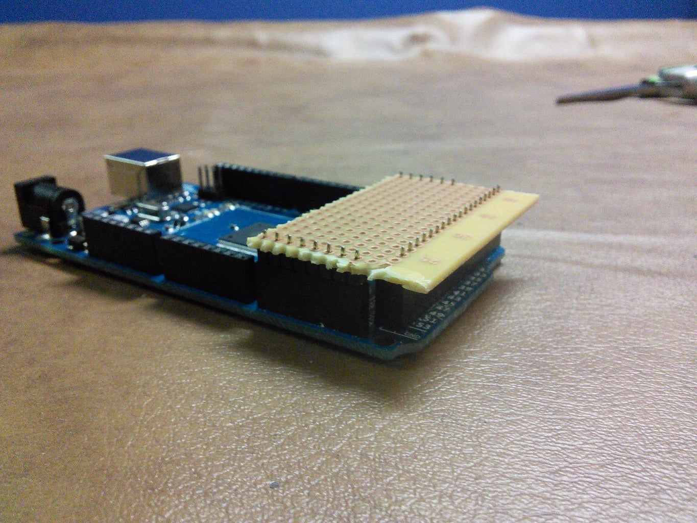

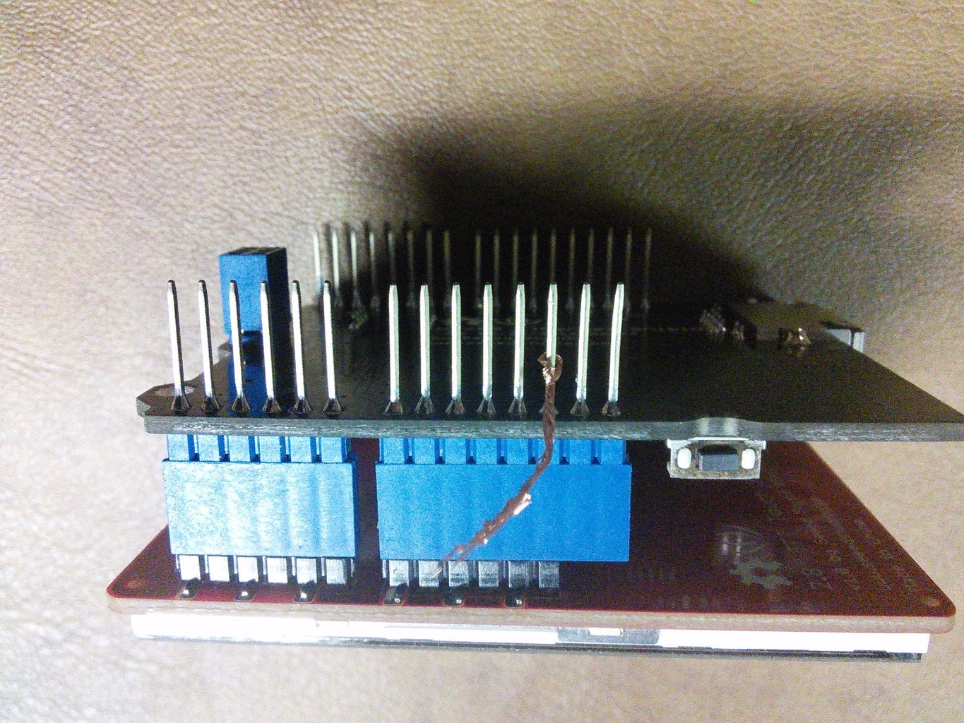
Now you have the headers, and the PCB, you are ready to solder. Make sure the headers are in the correct spots, as shown in previous step's pictures, and place your PCB on top of them, so they should have a perfect fit.
Now, simply add solder, joining the PCB and the male headers together, making sure the PCB's copper dots are facing upwards.
When you finish, you should have a 'Tail' shield that should work with other normal shields for Arduino.
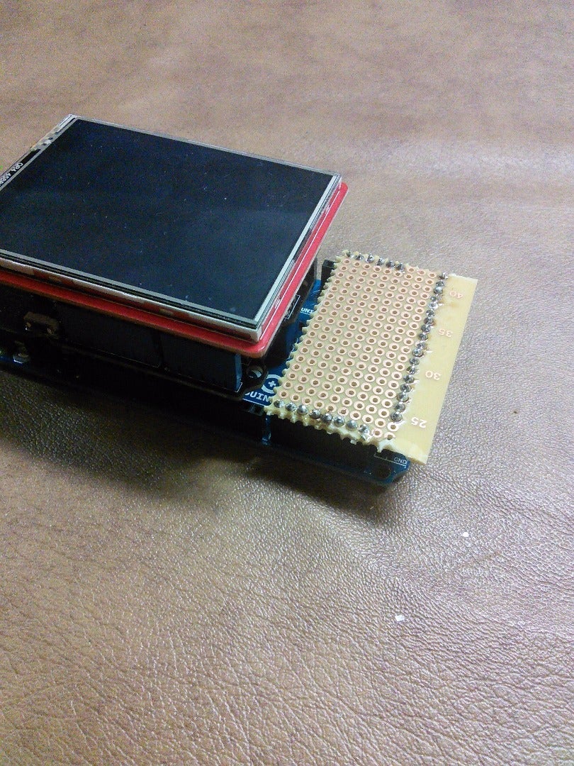
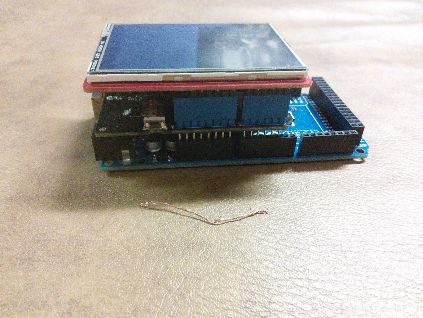
Now, as a test, place down your shields in the order: Ethernet > Touch Shield. If all has been done correct, they should fit together perfectly, with enough room to take out the Tail shield, or the other shields, in any order!
Step 5: PS/2 Keyboard - Testing Pinouts


Now it's time for the input method: a PS/2 keyboard. You could very much do this with a USB host shield, but those are a lot more expensive than a PS/2 connector and a PS/2 keyboard you may already have.
What you will want to do first, is cut the cable from the PS/2 connector. Mine I found at the bottom of a cable box, and it converted a PS/2 device to USB.
You should now see 4 wires, usually varying in colors. The colors in mine happen to be Green, Black, Red, and White. Plug in your Arduino (Not with the Tail attached to it we made in the previous step) and grab your wires. I attached some extending wires to make them longer, and so I could plugin them into your Arduino easier. Put the black wire in the GND port of your Arduino (Any one will do), as this is most likely to be ground. Grab your red wire and out it in the 5v port. Plug in your keyboard, and the lights should flash once, then go blank again. This means you have the power working. If this doesn't work, try doing different combinations until the keyboard is powered. Now it is up to finding the data pin, and the IRQ pin. Plug in one wire to pin 20, and the other to 21. If this doesn't work when you upload the code, then switch the wires.
Now, install the library and upload the code below to your Arduino. what should happen is once you start typing on the keyboard, the characters you type will show up in the Serial monitor. Remember, if it doesn't work, but your keyboard still powers on, try switching the data and IRQ pins.
The code:
<p>/*  PS2Keyboard library example<br>
  PS2Keyboard now requries both pins specified for begin()</p><p>  keyboard.begin(data_pin, irq_pin);

  Valid irq pins:
     Arduino Uno:  2, 3
     Arduino Due:  All pins, except 13 (LED)
     Arduino Mega: 2, 3, 18, 19, 20, 21
     Teensy 2.0:   All pins, except 13 (LED)
     Teensy 2.0:   5, 6, 7, 8
     Teensy 1.0:   0, 1, 2, 3, 4, 6, 7, 16
     Teensy++ 2.0: 0, 1, 2, 3, 18, 19, 36, 37
     Teensy++ 1.0: 0, 1, 2, 3, 18, 19, 36, 37
     Sanguino:     2, 10, 11

  for more information you can read the original wiki in arduino.cc
  at http://www.arduino.cc/playground/Main/PS2Keyboard
  or http://www.pjrc.com/teensy/td_libs_PS2Keyboard.html

  Like the Original library and example this is under LGPL license.

  Modified by Cuninganreset@gmail.com on 2010-03-22
  Modified by Paul Stoffregen
 June 2010
*/

#include
</p><p>const int DataPin = 8;
const int IRQpin =  5;</p><p>PS2Keyboard keyboard;</p><p>void setup() {
  delay(1000);
  keyboard.begin(DataPin, IRQpin);
  Serial.begin(9600);
  Serial.println("Keyboard Test:");
}</p><p>void loop() {
  if (keyboard.available()) {

    // read the next key
    char c = keyboard.read();

    // check for some of the special keys
    if (c == PS2_ENTER) {
      Serial.println();
    } else if (c == PS2_TAB) {
      Serial.print("[Tab]");
    } else if (c == PS2_ESC) {
      Serial.print("[ESC]");
    } else if (c == PS2_PAGEDOWN) {
      Serial.print("[PgDn]");
    } else if (c == PS2_PAGEUP) {
      Serial.print("[PgUp]");
    } else if (c == PS2_LEFTARROW) {
      Serial.print("[Left]");
    } else if (c == PS2_RIGHTARROW) {
      Serial.print("[Right]");
    } else if (c == PS2_UPARROW) {
      Serial.print("[Up]");
    } else if (c == PS2_DOWNARROW) {
      Serial.print("[Down]");
    } else if (c == PS2_DELETE) {
      Serial.print("[Del]");
    } else {

      // otherwise, just print all normal characters
      Serial.print(c);
    }
  }
}</p>
Library:
Attachments

Step 6: PS/2 Keyboard - Soldering


Now it's time to get the working keyboard looking more permanent.
First, take note of what wires go where. Next, take all the wires out and put in your Tail shield (See why I had you take note of where everything was?). Looking from the back of your Arduino and its Tail, all the way to the back left should be ground (GND). If it's not, send a picture of your defective Arduino, then rewire things so it will work properly.
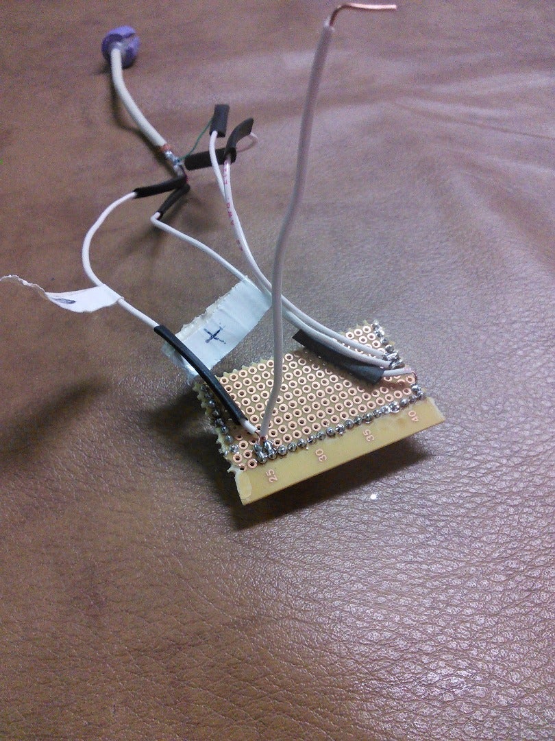
Jokes aside, get your PS/2 connector's ground wire you took note of previously, and put it in the dot forward of that ground pin and the header connecting to it. Solder the wire down to the copper dot, and make a bridge to the header connecting to the ground pin on the Arduino. Also remember to trim the wire as necessary. Now do the same thing, but with the 5v wire to the bottom right header.
Now, again looking from the back of the Arduino, locate the digital 20 and 21 pins, and solder the corresponding wires from the connector both one dot left of the solder on the header, and again, make a bridge to the header location. This can be tricky, so make sure there is NO unwanted solder bridges in between connections. Now, plug in your keyboard, and try it out with the same program in the last step. If all is working, you can proceed to the next step!
Step 7: Reset Feature

Now seems to be a good time for a little feature I decided would be good time to implement a simple, but pretty useful feature. This is the ability to reset the device (As in pressing the 'reset' button on the Arduino board) with a command inside the terminal itself. This is very simple.
First, get a small bit of stranded wire and wrap it around where the male part of the header on the Ethernet shield would go into the RESET pin in the Arduino. Make sure this is not touching ANY other wires, or has a possibility to. I recommend twisting the wire quite a bit, to form tension.
Now, head over to your Tail shield. (Looking from the back of the Arduino/Tail) Solder a bit of regular 22 gauge solid core wire to the direct right of where the ground wire is for the keyboard, and make a bridge one dot backwards to the edge of the board going to Digital pin 53. Now solder that wire to the stranded wire, and everything should be good.
Again, check for any unwanted solder bridges. I recommend keeping the shields on the Arduino at almost all times, just to keep the stranded wire from coming off.
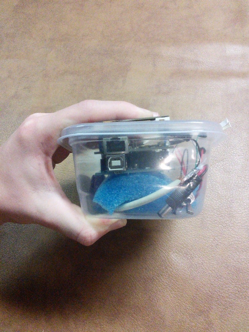
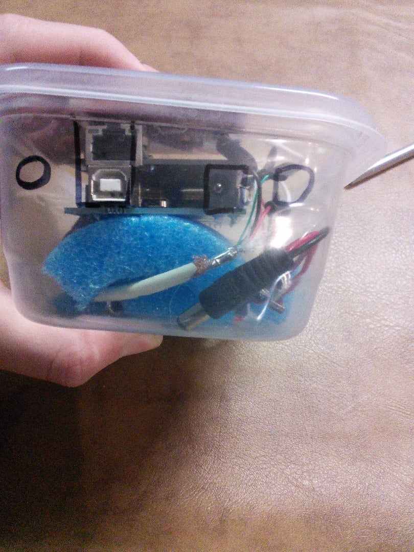
Step 8: Internal Power - Connectors


This, the internal power, adds two 9v batteries to your terminal, which makes this much more practical for carrying around anywhere (Besides the fact you need a keyboard with you, and its not too small), as you don't need to plug in your terminal wherever you are.
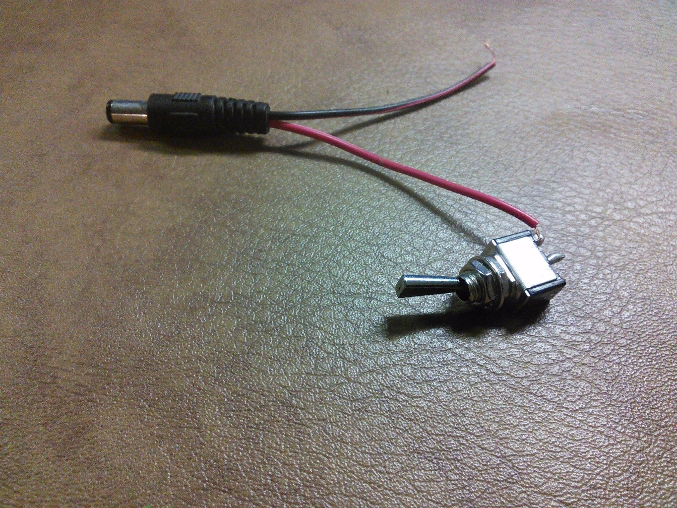
To make the simple battery on/off mechanism, you will start off with your small toggle switch, two 9v battery connectors and your DC power jack plug, making sure all the wires are stripped a little bit. In almost every case, the wire colors will be red and black, for all three units. Take the red wire from the DC power plug and solder it to one of the ends of the switch. Then, solder both of the red wires from the 9v battery connectors to the other end of the switch. To top it all off, solder all 3 black wires together, which you may want to put some electrical tape on this, or heat shrink tubing, to keep it from short circuiting.
To test this device, put two 9v batteries in the battery connectors, and the DC power plug into the Arduino. Turn the switch on, and you should see the Arduino turn on!
Now it's just time to mount the batteries.
Step 9: Internal Power - Mounting


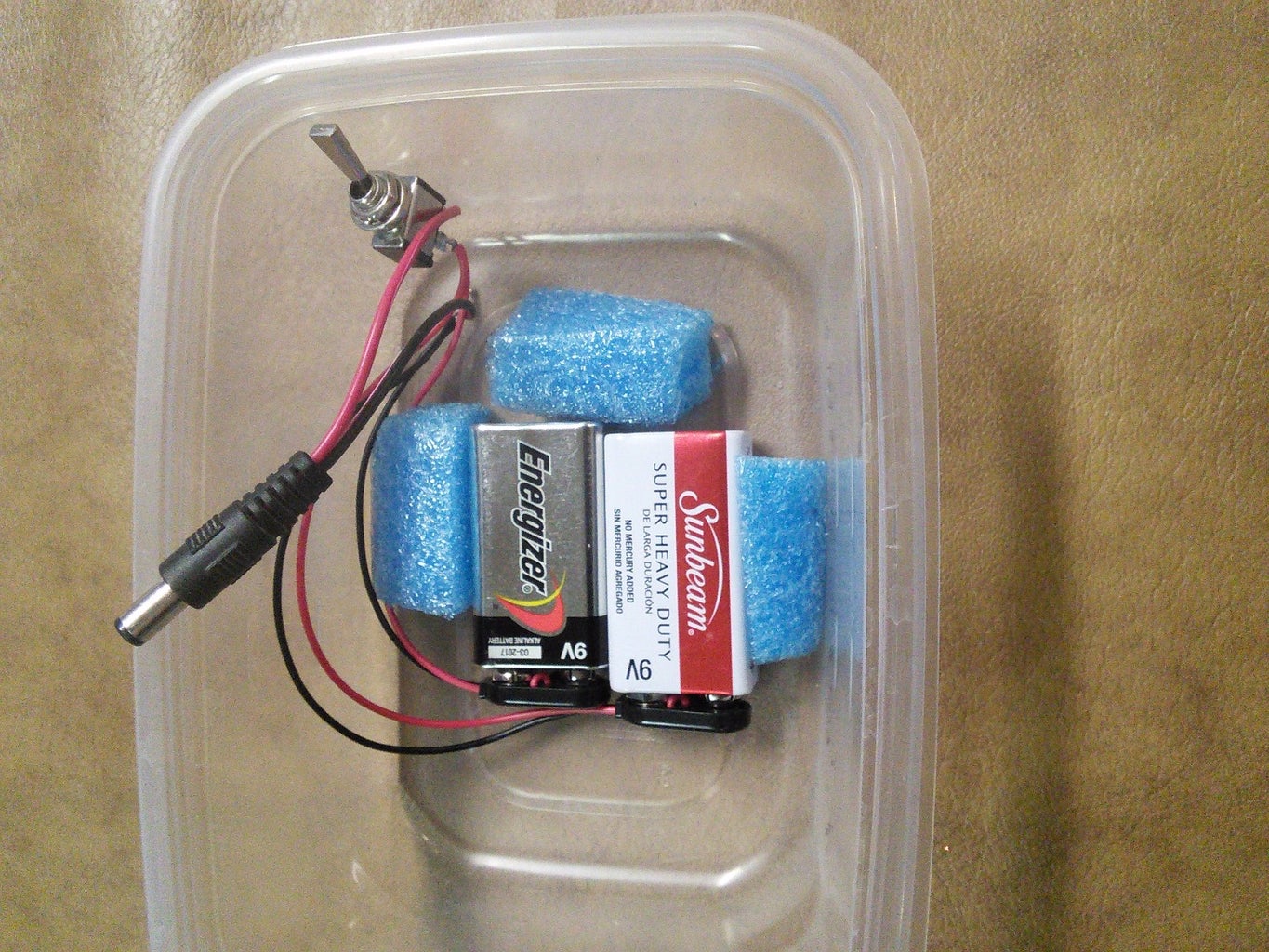


Now it's time to whip out your container of choice and a pool noodle. Get your scissors, and make a cut on one side of the pool noodle vertically. Now attempt to flatten it, without ripping it. I couldn't get too far, my mere attempts with an upside-down stool I was sitting on with it under didn't do too well, but it worked out. Get your Arduino, and cut the pool noodle so it's roughly the width of your Arduino, flattened. This will go on the underside of the Arduino to protect it from the slight possibility of short circuiting with batteries and just a spacer.
What is needed next, is placing your batteries in the center of your container at the bottom, and cutting some extra pool noodle to act as spacers on the sides, and bottom of your batteries. The spacers should apply some pressure to the batteries, but only enough to keep them in place. Use some hot glue to keep these down, but glue it with a low setting if possible, as hot glue loves eating through pool noodle foam.
Step 10: Mounting Everything - Vertical Spacing

Now, we're almost done! All this work has nearly paid off, but once you finish, it needs to look nice. To keep you from achieving your goals until longer, and to complete this project, it is time for the outer casing and mounting.
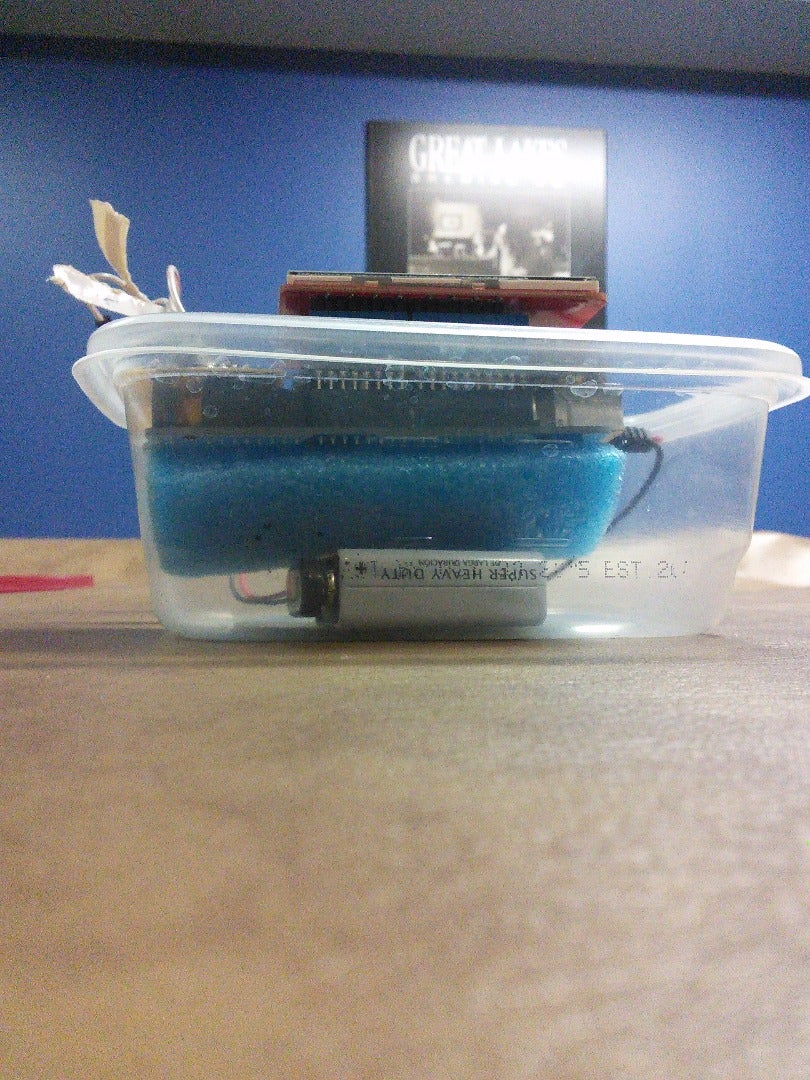
When everything is placed in the container very loosely, vertically it may be off. You want only a little bit of the TFT display poking out of the top when applying slight pressure from the top, so what may be needed is a trimming of the noodle spacer.
This was just to make sure you won't mess up cutting anything. You may need to cut almost all of the noodle, you may need to add more of the noodle. it depends on the noodle size and the container size.
Step 11: Mounting Everything - Cutting Top Holes


Cutting holes are slightly important, unless you want a plastic box with a whole bunch of useless electronics in it. (I am kidding, you need the holes)
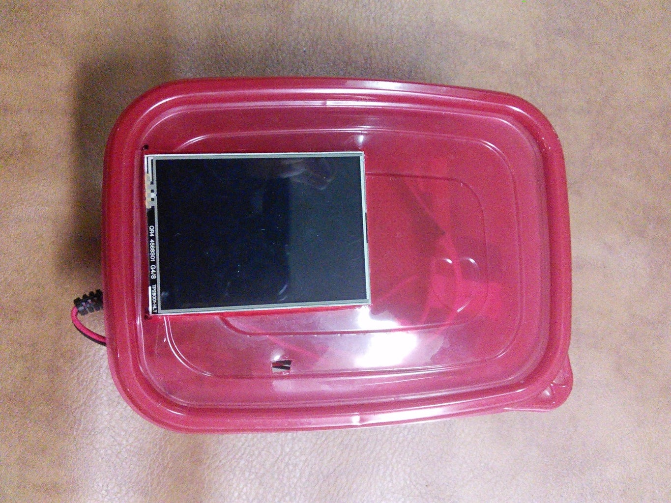
First let's start with the top. This is so the holes on the side will be better spaced vertically if the Arduino/Shields. If you don't know what I am talking about, just try and trust me, it will work out. What you will need to do, is line everything up inside the casing. You will want the bottom of the TFT monitor to be parallel with the container, so it looks nice.
Once you have everything lined up, carefully put the top of the container on, and mark where the corners of the screen are. You will notice on the Seeed Studio 2.8" TFT Touch Display, there is a red circuit sticking out at the bottom/below the screen itself sticking out a little bit. Mark just at the insides of those extrusions, so the entire screen will be sticking out once placed on the rest of the device. Take the top off of the screen, and bring it to a safe surface to cut a hole at your marks. Also, cut a small hole enough to glue/screw your small switch for the batteries into.
When the top is placed on the body of the device, everything should fit relatively nicely.
Step 12: Mounting Everything - Cutting Side Holes

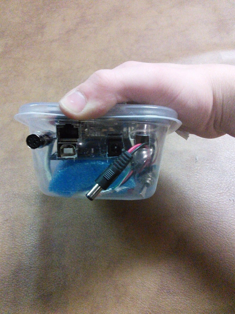


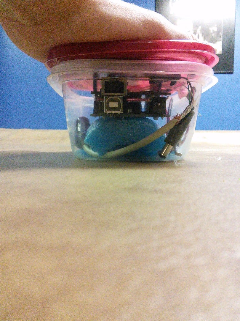
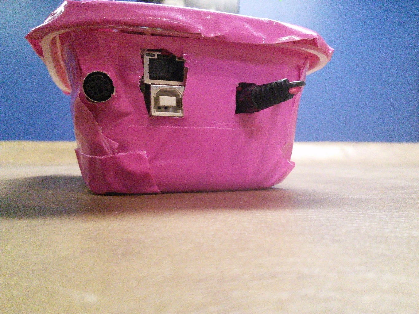
Side holes are necessary for, well, all connections, like the PS/2 keyboard, Ethernet, Arduino USB programming plug, and DC power.
While the top of your container is on, and Arduino with ALL shields are in the container as well, Start marking with something like a pen or Sharpie (Or cut right away, though not recommended) where the DC power jack is, along with the Arduino's USB port for programming/power, Ethernet port, and PS/2 connection port. For the PS/2 connection port you may need to guess as I did. You will also need a small hole next to the DC power hack hole, for the wire with the plug on it to some out and plug into the port. This hold can be around half the size to the same size as the DC power jack hole.
Once everything is marked out, take out the Arduino/Shields, and all battery things. You can now Cut with your X-Acto knife on your marks. I recommend cutting a little bit smaller than your marks, so you can touch up more accurately when lining up your holes with your Arduino/Shields.
Now put everything back in, and make sure everything aligns correctly. This would be a good time to touch up any holes.
The PS/2 connector, however, can not really just be placed in. This can be solved with some hot glue, so you can apply generously, you won't be able to take this connector out, by the way.
Step 13: Code!
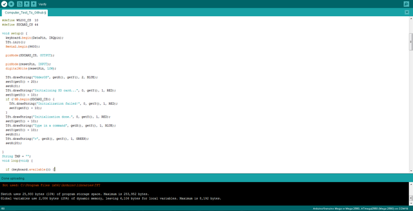

When building a project, software is what ties the project together. You could have an amazing looking terminal, but it doesn't do anything. That's not what you came here to build. You came here for an expandable, working terminal. And that's what is going to do.
Attached is a link to Github with some code , that has a few commands. It doesn't do too much in the ways of advanced calculations and predicting when the next time you will fall down the stairs, but you could possibly make it do so! The commands go as follows:
help - Displays all commands you can do. Example: help
rfile directory/file.extension - Outputs the contents of a file to the display. Leave the directory/directories blank if you just want to read a file in the root folder of the SD card. Example: rfile folder/test.txt
lfile directory - Displays all files and directories with sizes to display. Sizes are to the right of file, and is a '/' if it is a directory. Example: lfile folder/another_folder
reset - Equivalent to pressing the 'Reset' button on your Arduino/any shields that may have one. Example: reset
cls - Clears the screen, it takes about 2.5 seconds for it to clear top to bottom and is ready for typing commands again.
Note: To make everything work, you will need to install some libraries. These libraries are at the bottom of this step, with my Github page.
Adding commands are as simple as follows:
At line about 138 of Terminal.ino, there is a function called 'runCommand(String args)'
This is where all of your commands go. Let's look at the 'rfile' command on line 154.
You should see something like this:
String tmp;
String tmp2;
  tmp2 = args;
  if (args.indexOf(" ") > -1) {
    tmp = args.substring(args.indexOf(" "));
    tmp2.replace(tmp, "");
    tmp2.replace(" ", ""); // first was " -"
    tmp = tmp2;
  } else {
    tmp = args;
  }

...

if (tmp == "rfile") {
if(args.indexOf(" ") == 5) {
      String temp = args.substring(6);
      Tft.drawString("Opening file.", getX(), getY(), 1, RED);
      setY(getY() + 10);
      setX(0);
      fileFunct("read", temp);
      temp = "";
    } else {
      Tft.drawString("Try: rfile file.txt", getX(), getY(), 1, RED);
      setY(getY() + 10);
      setX(0);
    }

  }

...

else {
    Tft.drawString("Unknown!", getX(), getY(), 1, RED);
    setY(getY() + 10);
    setX(0);
  }
Let's break this down to the bare bones.
We will start with the code at the beginning:
String tmp;
String tmp2;
tmp2 = args;
  if (args.indexOf(" ") > -1) {
    tmp = args.substring(args.indexOf(" "));
    tmp2.replace(tmp, "");
    tmp2.replace(" ", "");
    tmp = tmp2;
  } else {
    tmp = args;
  }
For starters,
String tmp;
String tmp2;
Are just setting variables, tmp and tmp2. These are reset every time a command is passed through, hence the abreviated name, 'temporary'.
tmp2 = args;
Makes a copy of what is inputted when the ENTER button is pressed, as 'args' is passed as the core input.
This small piece of code:
if (args.indexOf(" ") > -1) {Checks that the space character's index is more than -1, AKA there is a space character. Commands with no arguments will not have this.
Now time to look at this:
    tmp = args.substring(args.indexOf(" "));
    tmp2.replace(tmp, "");
    tmp2.replace(" ", "");
    tmp = tmp2;
This, in order of lines, does something like this:
Set the String 'tmp' to everything after and including the space character.
Next, get the copy of the entire command, tmp2, and remove all the argument's characters, so you are left with just the main command, without any arguments.
Now replace that pesky space character with nothing.
Then, set the String tmp to the value of tmp2.
After that small block of code you will see:
 else {
    tmp = args;
  }
Which says, because there is no args, set the variable 'tmp' to the value of 'args' so 'tmp' can be registered.
Now the code is ready to check what command is put it. Now time for the next block of code.
if (tmp == "rfile") {
    if(args.indexOf(" ") == 5) {
      String temp = args.substring(6);
      Tft.drawString("Opening file.", getX(), getY(), 1, RED);
      setY(getY() + 10);
      setX(0);
      fileFunct("read", temp);
      temp = "";
    } else {
      Tft.drawString("Try: rfile file.txt", getX(), getY(), 1, RED);
      setY(getY() + 10);
      setX(0);
    }

  }
The code:
if (tmp == "rfile") {Checks that the String 'tmp' (The main command block) is the command 'rfile'.
Moving on,
if(args.indexOf(" ") == 5) {Makes sure there is a space at the index of 5, which in this command it is right after 'rfile'. Since coding and numbers start at the index of 0, this number should be the length of the command. An example of this would be:
r -> 0
f -> 1
i -> 2
l -> 3
e -> 4
[Space] -> 5
String temp = args.substring(6);
This code creates a new String, again resetting every time the command function is run, that is equal to one integer more than the number you used in the last part. Ex: If the number was 5, like we used, this number will e 6. This creates the String temp any arguments. Ex: if the command, rfile folder, was put in, temp would be folder.
Now, as the following code is not needed in making your own commands with other functions, I will briefly skim over this.
      Tft.drawString("Opening file.", getX(), getY(), 1, RED);
      setY(getY() + 10);
      setX(0);
      fileFunct("read", temp);
      temp = "";
In order, line by line, this is what the code does:
It draws a String "Opening file." to the last X and Y value set.
This sets the Y value for use of the next time something is written to the screen 1 letter (or 10 pixels) downward.
The X value is set to 0, so the next time something is written to the screen, it is starting at the edge of the screen.
This is the main function of the rfile command. This is a void type function, that takes two Strings, which the first one has to be "read", and the file name is temp, or the arguments.
This just resets temp, in case something weird happens that is unexpected.
Now, the code is almost done for this command. There is two small parts left, which looks like this:
else {
      Tft.drawString("Try: rfile file.txt", getX(), getY(), 1, RED);
      setY(getY() + 10);
      setX(0);
    }
Which is called if there is no space character, or it is put in the wrong place.
This displays on the screen, "Try: rfile file.txt" in red, then creates a new line.
else {
    Tft.drawString("Unknown!", getX(), getY(), 1, RED);
    setY(getY() + 10);
    setX(0);
  }
This is called when the command is unknown.
This displays on the screen, "Unknown!" in red, then creates a new line.
Well, that's really it for how the commands work, I will soon be adding comments all over the code on Github, telling what everything does.
Github:
https://github.com/RubbaBoy/ArduinoTerminal
Note: I will be adding a lot more functions to this project, and updating things, so don't worry if something doesn't work properly, or want a new command.
Libraries:
PS/2 Keyboard Library:
http://www.pjrc.com/teensy/arduino_libraries/PS2Ke...
Seeed Studio 2.8'' TFT Touch Shield V1.0 Library:
https://github.com/Seeed-Studio/TFT_Touch_Shield_V...
Seeed Studio Ethernet Shield V2.0
Step 14: Aesthetics!
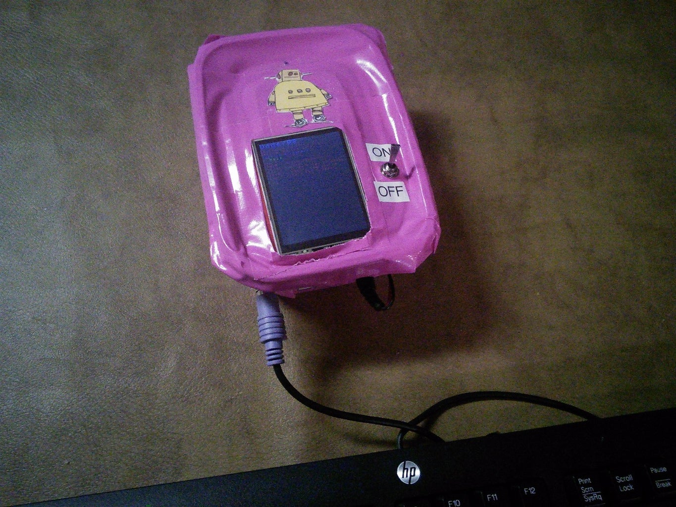


There is a reason I didn't put this before code, with the rest of hardware things. This is because this step is purely optional, I just did this to make it look pure awesome. Because the software is UdderOS, I put some pink duct tape on the terminal enclosure, to make it pink like an udder. I lastly printed out the Instructables logo on some card stock, and glued it above the screen, as there was some extra space there on the top. Then, I labels the on/off switch positions with a label maker.
Step 15: Conclusion
In the end, I learned many things. I learned that the TVout library is super annoying and I am almost never going to use it for anything again, I learned how to $10 on a keyboard that is almost useless for anything else BUT this project, and lastly, how to make a sweet, expandable terminal.
If I were to make this project again,I would probably make a wooden or metal enclosure, and space everything better. Right now it takes some fiddling and moving around with the Mega and shields for the display to properly fit in the top hole.
So this is the end, of that awesome Instructable you have bared to read through all the way (Or just briefly skimming through it), teaching you how to make something completely useless, but semi - educational.
If you have any ideas for commands, or have made your own functions, post the code in the comments below
Step 16: Bibliography
Here are all the links I could find that I used in the making of this project.
http://www.pjrc.com/teensy/td_libs_PS2Keyboard.htm...
http://playground.arduino.cc/Main/PS2Keyboard
http://www.seeedstudio.com/wiki/2.8''_TFT_Touch_Sh...

Participated in the
Arduino All The Things! Contest


