

Introduction: Arduino Traffic Lights


A few years ago I created a set of electronic traffic lights using the following parts list.
Part Quantity
- 100k Potentiometer 1
- 18k Resistor (1/4W) 1
- 1N4004 Diode 22
- 22µF Electrolytic Capacitor 1
- 2N3904 NPN Transistor 6
- 330 Resistor (1/4W) 8
- 4.7k Resistor (1/4W) 6
- 4017B Decade Counter 2
- LED (Green) 2
- LED (Red) 2
- LED (Yellow) 2
- NE555 Bipolar Timer 1
- Breadboard 2
- Jumper wires lots
The lights went through the basic pattern but did nothing else, and to change anything took ages.
It took me two days to create this and I was still not that happy with it.
Today I created another set of lights, this time using an Arduino, and the parts list now looks like this.
Part Quantity
- Arduino 1
- 220 Resistor (1/4W) 6
- LED (Green) 2
- LED (Red) 2
- LED (Yellow) 2
- Breadboard 1
- Jumper wires
Because everything is controlled by the Arduino, I could make it run a more realistic sequence, like the UK safer one, which goes a bit like this sequence
Set 1 Set 2:
- Red Green
- Red Amber
- Red/Amber Red
- Green Red
- Amber Red
- Red Red/Amber
- Red Green
I also wrote two sketches showing how code can be written differently.
All this and it only took me a few hours.
Step 1: Project Scope


This Instructable is to offer two things.
(I am not going to explain the wiring of my original circuit, but I have added the circuit diagram here for completeness.)
- How to control traffic lights with an Arduino.
- How sections of code can be written differently with the exact same result.
Step 2: Wiring It Up:
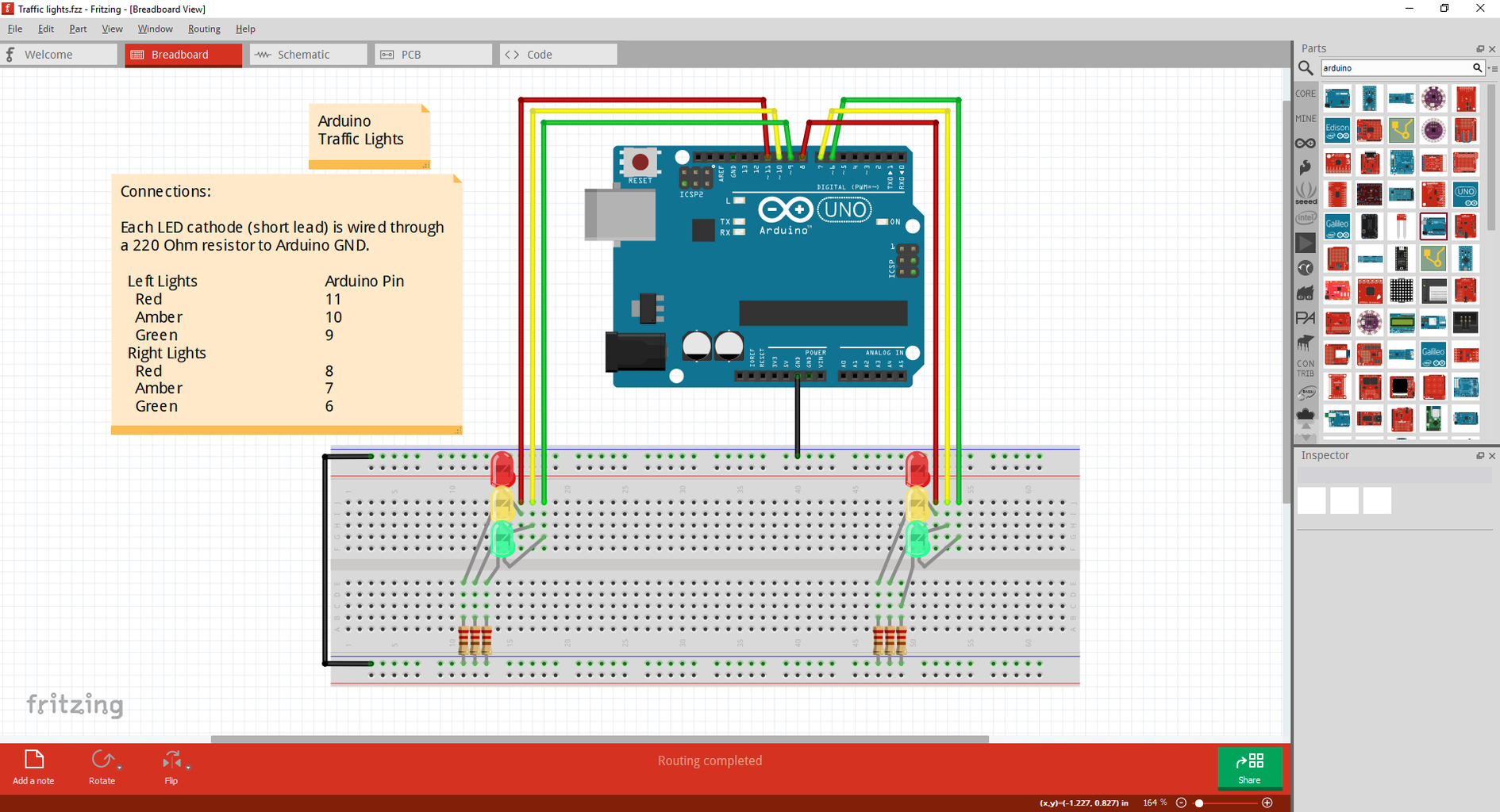

Each LED cathode (short lead) is wired through a 220 Ohm resistor to Arduino GND
Left Lights Arduino Pin
- Red 11
- Amber 10
- Green 9
Right Lights
- Red 8
- Amber 7
- Green 6
Step 3: Arduino Sketch No 1: Walk Through
Prior to the Setup routine, we start with defining all code variables
When defining variable to use in our code, it makes sense to use meaningful names for them, that way we know what we are using at any point in our code.
The method that we normally use is called Camel case.
This is done by taking all of the words that we want to call our variable name, making one long word but capitalising all of the words except the first one.
So, a variable called 'this is the variable for horizontal axis' becomes 'thisIsTheVariableForHorizontalAxis' and is still quite easy to read.
The code is compiled before uploading to the Arduino and therefore uses no more space for 'thisIsTheVariableForHorizontalAxis' than it does for 'x'.
However, there is also a convention for defining variables that will not change in their lifetime, these are called constants and normally written in Upper Case with underscores instead of spaces, these are all prefixed with 'const' in the code.
These are only conventions. they are not mandatory, they just make our code easier to follow.
In this section, we also define what pins that we are going to use on the Arduino.
This is a simple sketch and we are defining consecutive pins 6 to 11.
By defining the pins here we do not have to worry about number they relate to later on; we can just use their name.
int switchingDelay = 1000; //delay for the light transitions
const int RED_LEFT = 11;//define the LEDs with meaningful names
const int AMBER_LEFT = 10;
const int GREEN_LEFT = 9;
const int RED_RIGHT = 8;
const int AMBER_RIGHT = 7;
const int GREEN_RIGHT = 6;
In the setup routine, we then tell the compiler what we are doing with which pin.
In our case we are setting all the pins that we require to OUTPUT.
void setup()
{
pinMode(RED_LEFT, OUTPUT);//assign the LEDs to the Arduino
pinMode(AMBER_LEFT, OUTPUT);
pinMode(GREEN_LEFT, OUTPUT);
pinMode(RED_RIGHT, OUTPUT);
pinMode(AMBER_RIGHT, OUTPUT);
pinMode(GREEN_RIGHT, OUTPUT);
//Next is our first bit of working code as far as the traffic lights are concerned.
//We set all LEDs to off.
//We do not really need to do this as they will change quite quickly anyway, but it is good to initialise in this way.
digitalWrite(RED_LEFT, LOW);//turn all lights off
digitalWrite(AMBER_LEFT, LOW);
digitalWrite(GREEN_LEFT, LOW);
digitalWrite(RED_RIGHT, LOW);
digitalWrite(AMBER_RIGHT, LOW);
digitalWrite(GREEN_RIGHT, LOW);
}
That is the end of the setup routine and now we move to the loop routine, which will keep running until we remove the power.
This is from our sequence mentioned above.
Remember that some are already on or off at any time.
void loop()
{
digitalWrite(RED_LEFT, HIGH); //Red Green
digitalWrite(GREEN_RIGHT, HIGH);
delay(switchingDelay);//pause sequence
digitalWrite(AMBER_RIGHT, HIGH); //Red Amber
digitalWrite(GREEN_RIGHT, LOW);
delay(switchingDelay);
digitalWrite(RED_RIGHT, HIGH); //Red/Amber Red
digitalWrite(AMBER_RIGHT, LOW);
digitalWrite(AMBER_LEFT, HIGH);
delay(switchingDelay);
digitalWrite(RED_LEFT, LOW); //Green Red
digitalWrite(AMBER_LEFT, LOW);
digitalWrite(GREEN_LEFT, HIGH);
digitalWrite(AMBER_RIGHT, LOW);
delay(switchingDelay);//double pause for Green on
delay(switchingDelay);
digitalWrite(AMBER_LEFT, HIGH); //Amber Red
digitalWrite(GREEN_LEFT, LOW);
delay(switchingDelay);
digitalWrite(RED_LEFT, HIGH); //Red Red/Amber
digitalWrite(AMBER_LEFT, LOW);
digitalWrite(AMBER_RIGHT, HIGH);
delay(switchingDelay);
digitalWrite(RED_RIGHT, LOW); //Red Green
digitalWrite(AMBER_RIGHT, LOW);
digitalWrite(GREEN_RIGHT, HIGH);
digitalWrite(RED_LEFT, HIGH);
digitalWrite(AMBER_LEFT, LOW);
delay(switchingDelay);
delay(switchingDelay);
}
And that is all that is required.
The sketch file is included below for you to try and experiment with.
Step 4: Arduino Sketch No 2: Walk Through
We are using two variables here, but they still have meaningful names.
int switchingDelay = 2000; //delay for the light transitions
The next variable may seem a little strange to those who have not seen a two dimensional array before.
Think of it like a spreadsheet where you have rows and columns.
The variable is defined as SWITCHING_MODE[2][30], which means we have 2 rows and 30 columns.
If you have more columns listed in your code than you have defined, you will get a compiler error.
Create a two dimensional array to hold the pin numbers and their associated state.
The first row holds the Arduino pin numbers in the sequence of the traffic lights that we want.
The second row is for the state of that pin during the sequence, 0 = off, 1 = on.
The -1 is used to denote a pause in the sequence.
const static int SWITCHING_MODE[2][30] =
{
{11, 6, -1, 7, 6, -1, 8, 7, 10, -1, 11, 10, 9, 7, -1, -1, 10, 9, -1, 11, 10, 7, -1, 8, 7, 6, 11, 10, -1, -1},
{1, 1, -1, 1, 0, -1, 1, 0, 1, -1, 0, 0, 1, 0, -1, -1, 1, 0, -1, 1, 0, 1, -1, 0, 0, 1, 1, 0, -1, -1}
};
In the setup routine, we then tell the compiler what we are doing with which pin.
In our case we are setting all the Arduino pins that we require to OUTPUT, but this time we are using a loop to achieve this.
That is why we used consecutive numbers for the Arduino pins.
While we are in the loop we also set all LEDs to off.
void setup()
{
for (int i = 5; i <= 11; i++)//loop through all of the pin numbers for this sketch
{
pinMode(i, OUTPUT);//assign the right LEDs to the Arduino as output
digitalWrite(i, LOW);//set LED to off
}
}
That is the end of the setup and now we move to the loop routine, which will keep running until we remove the power.
Our code this time is somewhat shorter than before because the sequence is all wrapped up in our two dimensional array.
What we do here is loop through all 30 elements of the row,
SWITCHING_MODE[0][i] gives us the Arduino pin number that has an LED on it.
SWITCHING_MODE[1][i] gives us the state for that pin in our sequence.
If we come across a -1 in the first row, then we run the else part of the routine which is our delay between state changes in the sequence.
void loop()
{
for (int i = 0; i < 30; i++)//loop through all elements of the array
{
if (SWITCHING_MODE[0][i] != -1)//test for a pause command
{
digitalWrite(SWITCHING_MODE[0][i], SWITCHING_MODE[1][i]);//send the correct state to the pin
}
else
{
delay(switchingDelay);//pause sequence
}
}
}
Step 5: All Done


And that is it. Two different ways to write code to do exactly the same thing.
I hope that this has been informative.
I used the Traffic Lights as an example because they are quite simple in their operation and makes the code somewhat easier to explain to someone who may not have seen or used this type of approach.


