

Introduction: Arduino Tutorial - Numeric Keypads

More by the author:


About: Technical person. Visit http://tronixstuff.com for Arduino and other tutorials, projects, kits, reviews and more. VK3FJBX http://arduinoworkshop.com
This is an example of one of my Arduino tutorials.
Numeric keypads can provide a simple end-user alternative for various interfaces for your projects. Or if you need a lot of buttons, they can save you a lot of time with regards to construction. We’ll run through connecting them, using the Arduino library and then finish with a useful example sketch.
Getting Started
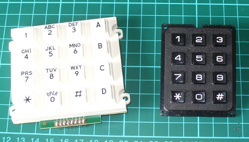
Numeric keypads are available from many retailers, and no matter where you get them from, make sure you can get the data sheet, as this will make life easier when wiring them up. Shown above are two examples for our tutorial, from Futurlec (slow and cheap).
Again, the data sheet is important as it will tell you which pins or connectors on the keypad are for the rows and columns, for example the black keypad shown above. If you don’t have the data sheet – you will need to manually determine which contacts are for the rows and columns.
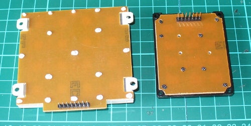
This can be done using the continuity function of a multimeter (the buzzer). Start by placing one probe on pin 1, the other probe on pin 2, and press the keys one by one. Make a note of when a button completes the circuit, then move onto the next pin. Soon you will know which is which. For example, on the example keypad pins 1 and 5 are for button “1″, 2 and 5 for “4″, etc… Furthermore some keypads will have the pins soldered to the end, some will not. With our two example keypads, the smaller unit had the pins – and we soldered pins to the large white unit.
At this point please download and install the keypad Arduino library. Now we’ll demonstrate how to use both keypads in simple examples.
Using a 12 digit keypad
We’ll use the small black keypad from Futurlec, an Arduino Uno-compatible and an LCD with an I2C interface for display purposes. If you don’t have an LCD you could always send the text to the serial monitor instead.
Wire up your LCD then connect the keypad to the Arduino in the following manner:
// keypad type definition
As you need to change the numbers in the arrays rowPins[ROWS] and colPins[COLS]. You enter the digital pin numbers connected to the rows and columns of the keypad respectively. Furthermore, the array keys stores the values displayed in the LCD when a particular button is pressed. You can see we’ve matched it with the physical keypad used, however you can change it to whatever you need. But for now, enter and upload the following sketch once you’re satisfied with the row/pin number allocations...
And the results of the sketch are shown in this video:
So now you can see how the button presses can be translated into data for use in a sketch. We’ll now repeat this demonstration with the larger keypad.
Using a 16 digit keypad
We’ll use the larger white 4×4 keypad from Futurlec, an Arduino Uno-compatible and for a change the I2C LCD from Akafugu for display purposes. (We reviewed these previously). Again, if you don’t have an LCD you could always send the text to the serial monitor instead. Wire up the LCD and then connect the keypad to the Arduino in the following manner:
And now for an example project, one which is probably the most requested use of the numeric keypad…
Example Project – PIN access system
The most-requested use for a numeric keypad seems to be a “PIN” style application, where the Arduino is instructed to do something based on a correct number being entered into the keypad. The following sketch uses the hardware described for the previous sketch and implements a six-digit PIN entry system. The actions to take place can be inserted in the functions correctPIN() and incorrectPIN(). And the PIN is set in the array char PIN[6]. With a little extra work you could create your own PIN-change function as well.
The project is demonstrated in this video:
Conclusion
So now you have the ability to use twelve and sixteen-button keypads with your Arduino systems. I’m sure you will come up with something useful and interesting using the keypads in the near future.
If you enjoyed this tutorial, check out the rest and much more at tronixstuff.com.
Numeric keypads can provide a simple end-user alternative for various interfaces for your projects. Or if you need a lot of buttons, they can save you a lot of time with regards to construction. We’ll run through connecting them, using the Arduino library and then finish with a useful example sketch.
Getting Started
Numeric keypads are available from many retailers, and no matter where you get them from, make sure you can get the data sheet, as this will make life easier when wiring them up. Shown above are two examples for our tutorial, from Futurlec (slow and cheap).
Again, the data sheet is important as it will tell you which pins or connectors on the keypad are for the rows and columns, for example the black keypad shown above. If you don’t have the data sheet – you will need to manually determine which contacts are for the rows and columns.
This can be done using the continuity function of a multimeter (the buzzer). Start by placing one probe on pin 1, the other probe on pin 2, and press the keys one by one. Make a note of when a button completes the circuit, then move onto the next pin. Soon you will know which is which. For example, on the example keypad pins 1 and 5 are for button “1″, 2 and 5 for “4″, etc… Furthermore some keypads will have the pins soldered to the end, some will not. With our two example keypads, the smaller unit had the pins – and we soldered pins to the large white unit.
At this point please download and install the keypad Arduino library. Now we’ll demonstrate how to use both keypads in simple examples.
Using a 12 digit keypad
We’ll use the small black keypad from Futurlec, an Arduino Uno-compatible and an LCD with an I2C interface for display purposes. If you don’t have an LCD you could always send the text to the serial monitor instead.
Wire up your LCD then connect the keypad to the Arduino in the following manner:
- Keypad row 1 to Arduino digital 5
- Keypad row 2 to Arduino digital 4
- Keypad row 3 to Arduino digital 3
- Keypad row 4 to Arduino digital 2
- Keypad column 1 to Arduino digital 8
- Keypad column 2 to Arduino digital 7
- Keypad column 3 to Arduino digital 6
// keypad type definition
As you need to change the numbers in the arrays rowPins[ROWS] and colPins[COLS]. You enter the digital pin numbers connected to the rows and columns of the keypad respectively. Furthermore, the array keys stores the values displayed in the LCD when a particular button is pressed. You can see we’ve matched it with the physical keypad used, however you can change it to whatever you need. But for now, enter and upload the following sketch once you’re satisfied with the row/pin number allocations...
And the results of the sketch are shown in this video:
So now you can see how the button presses can be translated into data for use in a sketch. We’ll now repeat this demonstration with the larger keypad.
Using a 16 digit keypad
We’ll use the larger white 4×4 keypad from Futurlec, an Arduino Uno-compatible and for a change the I2C LCD from Akafugu for display purposes. (We reviewed these previously). Again, if you don’t have an LCD you could always send the text to the serial monitor instead. Wire up the LCD and then connect the keypad to the Arduino in the following manner:
- Keypad row 1 (pin eight) to Arduino digital 5
- Keypad row 2 (pin 1) to Arduino digital 4
- Keypad row 3 (pin 2) to Arduino digital 3
- Keypad row 4 (pin 4) to Arduino digital 2
- Keypad column 1 (pin 3) to Arduino digital 9
- Keypad column 2 (pin 5) to Arduino digital 8
- Keypad column 3 (pin 6) to Arduino digital 7
- Keypad column 4 (pin 7) to Arduino digital 6
- the extra column in the array char keys[]
- the extra pin in the array colPins[]
- and the byte COLS = 4.
And now for an example project, one which is probably the most requested use of the numeric keypad…
Example Project – PIN access system
The most-requested use for a numeric keypad seems to be a “PIN” style application, where the Arduino is instructed to do something based on a correct number being entered into the keypad. The following sketch uses the hardware described for the previous sketch and implements a six-digit PIN entry system. The actions to take place can be inserted in the functions correctPIN() and incorrectPIN(). And the PIN is set in the array char PIN[6]. With a little extra work you could create your own PIN-change function as well.
The project is demonstrated in this video:
Conclusion
So now you have the ability to use twelve and sixteen-button keypads with your Arduino systems. I’m sure you will come up with something useful and interesting using the keypads in the near future.
If you enjoyed this tutorial, check out the rest and much more at tronixstuff.com.


