

Introduction: Arduino Universal Bluetooth Connect - Control Your Arduino With Your Android Device

I always wanted to easily control my Arduino with my Smartphone, but i never found the perfect solution for doing so. I don't want to say that this is perfect, but it does what i want it to do....well not completely but I'm close... I think.
In this Instructable I will show you how to Control your Arduino with your Smartphone. I used the MIT App Inventor 2 for programming the Android App. You will not have to make any coding if you don't want to but i will show you how to use my app with any of your Projects.
I have parted this Instructables in 5 Parts:
Part 1: Arduino Bluetooth Basics
I will explain how to connect your Arduino with your Bluetooth Device and how to connect your Bluetooth Module with your Android. Also we will make a simple Communication between your Android Device and your PC.
Part 2: The UBTC Protocol
I will explain the UBTC Protocol. I use this to communicate between the Andoid App and the Arduino Code.
Part 3: The Basic Bluetooth Connect App
This is the App to Control your Arduino. I will explaint it and also explain the sketch and what you may have to edit.
Part 4: Create you own stuff
I will explain what you will have to edit in the Arduino Sketch to use the BBTC App with your Project.
Part 5: Conclusion and To Do List
Conclusion and To Do List.... duuh :)
Soo...
Looks like i will have to explain a lot...so let´s go!
--
If you like this Instructable, please consider voting for me at the Arduino all the Things Contest!!!
--
NOTES:
I'm sorry for my bad English, if you find a big spelling error please notify me and i will correct it. :)
There are two app featured in this Instructable:
1. The Easy Bluetooth Connect App:
This is the small App and features just the direct communication with the Serial Monitor if you have the "SoftwareSerialExampleUBTC.ino" uploaded to your Arduino.
2. The Basic Bluetooth Connect App:
This ist the big App wich can control all of your I/O pins and much more. You will need to upload the "UBTC.ino" to your Arduino for this App to work.
Both Apps are still not finished and i will work on both of them. They will be updated and you will always find the newest version on this page. :) For my To Do List look at Step 15. If have suggestion what i should add in future versions, let me know in the comments.
Step 1: Part 1: Arduino Bluetooth Basics - Materials


Part 1:
Let's make simple Communication between your Arduino and your Android Device. I am using Software Serial for the Bluetooth Module instead of the RX/TX pins(0/1). If you already know how to make such a Communication, you can skip this Part.
--
You will need:
- 1 Arduino or Arduino compatible device (for beginners: use an Arduino UNO)
- 1 Arduino to PC cable
- 1 PC wit the Arduino IDE ( Maybe a better one than above :)
- 1 Android Device with Bluetooth
- 1 HC-05 or HC-06 or any Arduino compatible Bluetooth Device
- 1 Breadbord
- Wires
- Led(s) wit Resistor(s)
- Whatever you want to control with your Arduino
- Fun
- Much more Fun
Step 2: Part 1: Arduino Bluetooth Basics - Connection


Let's Connect the Bluetooth Module to your Arduino and your Arduino to your PC.
--
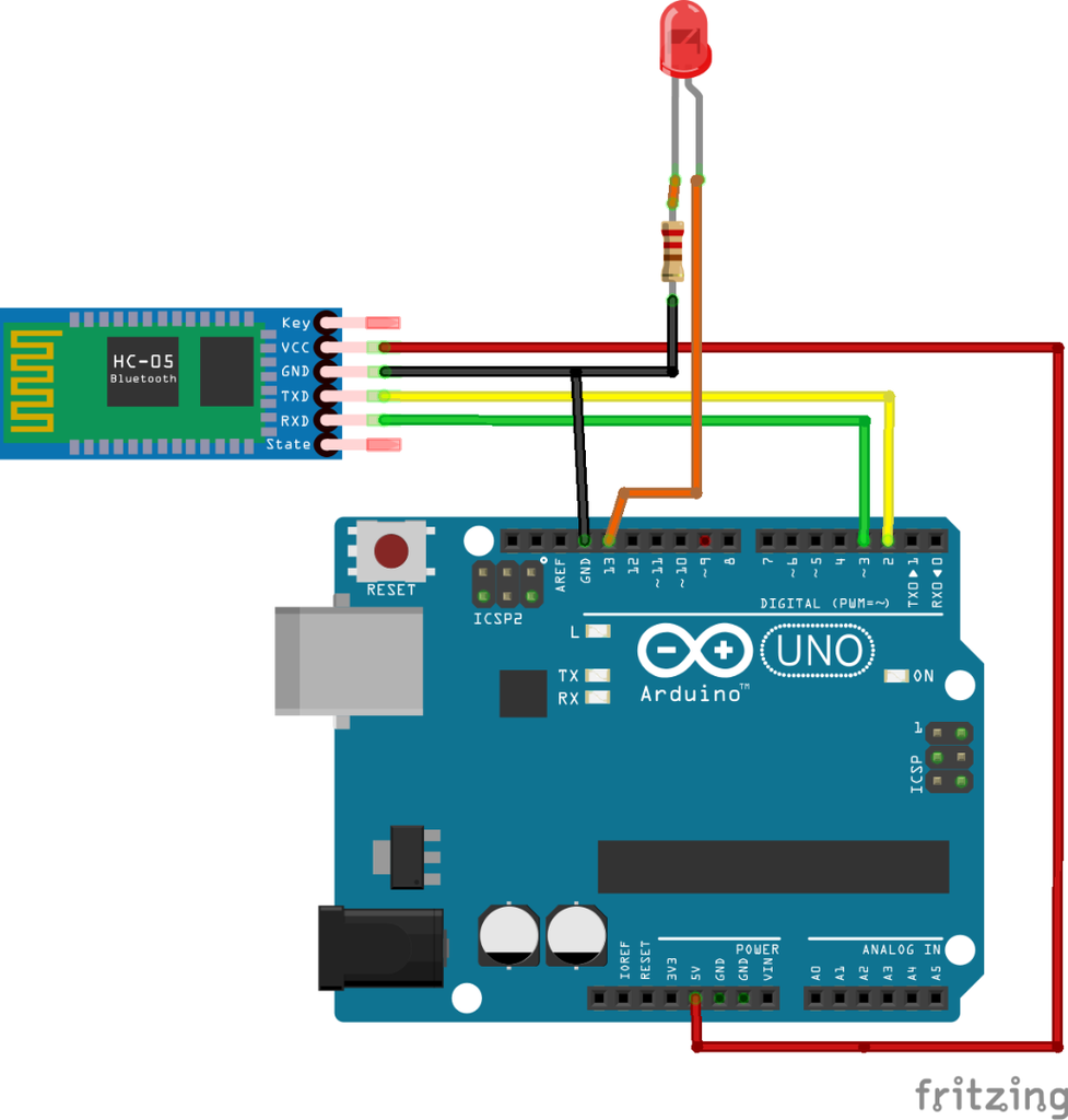
The Connection is actually very easy:
- Connect your Bluetooth Modules GND to Ground
- Connect your Bluetooth Modules VCC to 5V
- Connect your Bluetooth Modules TX to Pin 2
- Connect your Bluetooth Modules RX to Pin 3
- Connect your Arduino to your PC
Step 3: Part 1: Arduino Bluetooth Basics - Arduino Code


For the Code we will use a slightly modified version of Tom Igoe and Mikal Hart's SoftwareSerialExample.
Just download the "SoftwareSerialExampleUBTC.ino" to your PC and open with the latest Arduino IDE. You may have to change the baud rate of your BT module. You should find the correct baud rate in your modules specifications(If you can't find it, ask for it in the comments maybe someone else knows the baud rate you need). My module has a baud rate of 9600 so I set "BTBaudRate" to 9600. After that upload the Sketch to your Arduino and open the Serial monitor. Make sure that you have the Serial Monitor's baud rate at 9600.
What this sketch does is just simply sending everything it gets from the Bluetooth Module to your PC via the Serial Port.
Attachments

Step 4: Part 1: Arduino Bluetooth Basics - the Easy Bluetooth Connect App


This is a very simple App. What ever you write into the text box will be send to you Bluetooth module if you press "Send". Just download the EasyBTC.apk to your Smartphone and install it. You may have to turn on "Unknown sources". To do that go to "Settings" -> "Security" -> "Device administration" -> "Unknown sources".
Before you can use the App you have to pair your smartphone with your Bluetooth module:
- Go to your devices Bluetooth settings
- Enable Bluetooth
- Find your Bluetooth Module (mine is called "HC-06" but yours could have a name like: "A1:B2:C3:D4:E5:F6")
- Click on it to pair with your Phone
- You may have to enter a Code (Standard are "1234" or "0000")
Done!!!
Attachments
Step 5: Part 1: Arduino Bluetooth Basics - the First Communication


Let's make the Communication between your Arduino and your Android Phone.
- Now open the Easy Bluetooth Connect App
- Press "Select BT Module"
- Select your Bluetooth Module
- Press "Connect to BT Module". Wait until the Button turns green.
- Now Write whatever you want into the textbox and
- Press "Send".
- You should see what you wrote appear on you Arduinos Serial Monitor.
This was the first Step. I ope you liked it if you want you can take a look into the EasyBTC.aia if you want to find out more what the Easy Bluetooth Connect App does. You have to go to the MIT App Inventor 2 website, log in and select Import Project.
Attachments
Step 6: Part 2: the UBTC Protocol - the Overview

The Universal Bluetooth Communication Protocol is the Protocol with wich your Basic Bluetooth Communication App on your Smartphone and your Arduino communicate. The App sends one String of data via your Bluetooth Module and the Arduino parses it back into the individual Data Blocks.
The App sends 21 data Parts compared into one String to the Arduino. Between every "real" data there is a parsing Block. The first one is called "$P0$", the second one "$P1$" and so on till "$P9$".
Question: JUST WHY???
To parse the individual data blocks back you need something that separates them. I chose $P0$(and so on...) because i don't think that this will ever be send as a individual data. If I would have used something like "1" to separate the Data blocks it would probably caused many errors.
For more information about the separation check "UBTC.ino".
I know that it's not perfect yet but i am working on a simpler solution. If there is more information needed for this Topic please let me know. Check Step 7 for an example and Step 14 for your own project.
Attachments
Step 7: Part 2: the UBTC Protocol - an Example


As seen in the Excel table on Step 6, if you want to use the "Pin" function (more information about this function in Step 10), Mode (or part0 or Data0) has to be "Pin". part1 (or Data1) is labeled with "The Pin". Here has to be the Pin number you want to change. part2 (or Data2) is "D" or "A". "D" for Digital and "A" for Analog so the Arduino knows if "digitalWrite(pin,value)" or "analogWrite(pin,value)" has to be used. And part3 (or Data3) is finally the value, either "0" or "1" or "0" to "255". The last data part is always "null" to avoid interference. You don't have to include a "null" but it reduces the errors significantly.
Example:
The Arduino gets: Pin$P0$13$P1$D$P2$1$P3$null
If the first Data part(part0) is "Pin", the void Pin is being executed (see pictures). part1 is "13", part2 is "D" and part3 is "1" so the pin 13 is set to HIGH with: digitalWrite(13,1); part4 is ignored :((
If you want to check if you understood it find out what the Arduino does if it gets:
1. Pin$P0$6$P1$A$P2$128$P3$null (easy)
2. Pin$P0$12$P1$D$P2$0$P3$null (hard...ish)
The solutions are on the last step :)
If there is more information needed for this Topic please let me know. Check Step 6 for the overview and Step 14 for your own project.
Step 8: Part 3: the Basic Bluetooth Connect App - the Arduino Sketch


The Connection is almost the same:
-Connect your Bluetooth Modules GND to Ground
-Connect your Bluetooth Modules VCC to 5V
-Connect your Bluetooth Modules TX to Pin 2
-Connect your Bluetooth Modules RX to Pin 3
-Connect your Arduino to your PC
-Maybe add an Led with Resistor to one of the Pins from Pin 4 to Pin 13
---
You can also use other Pins for the Bluetooth Module. I don't recommend using Pins 0 or 1 but you should just don't have anything connected to these pins if you want to upload any Code. If you use other Pins for your Bluetooth Module, you have to change "RX" and "TX" in the Arduino Sketch. Also make sure that the baud rates match. More information about these on Step 3.
When you open the Serial Monitor after uploading you will see:
Hello!
SerialReportStatus: 0
if you write "report" and hit Enter you will get:
Hello!
SerialReportStatus: 0
SerialReportStatus: 1
Now every data send to the Arduino will be displayed on the Serial Monitor. If you write "report" again you can turn the information off again. That's all you have to know about the Sketch at this Step. Check Step 14 for more information.
Attachments
Step 9: Part 3: the Basic Bluetooth Connect App - the Android App


This is the expanded version of the EBTC App. Pairing and connecting your Bluetooth Module with your Android Phone are the same. Check Step 4 for more information.
Once you have connected your Phone with your Bluetooth Module, click "Select Mode". Now select the mode you want to use *insertcaptainobvioushere*.
On/Off
Turn your digital pins on and off with your smartphone .I further explain On/Off on step 10.
Send Text to Serial
Make sure you have your Arduino Connected to your PC and opened your Serial Monitor. Now write something into the Textbox and hit "Send". You should see what you wrote appear on the Serial Monitor. Write "report" into the Serial Monitor to get more information about the transmission.
Send Text Raw
Basicly the function the EBTC App has. SerialReportStatus has to be 1 (write "report" into the Serial Monitor) so you see anything.
Open Garage
With this function and an relay you can easily open your Garage. Check Step 11.
Robot
You can control a simple robot with this function. I focus on small cars with two DC motors, controlled by an motor driver IC like the l293d. More about this on Step 12.
Your own Stuff
Check Part 4 for more information.
AnalogRead
//ToDo
//I'm working on that function
Attachments
Step 10: Part 3: the Basic Bluetooth Connect App - the On/Off Function


I thinks this explains it self. If you press the "Off" button, it turns the Led on and changes to a green "On" button... If you move the sliders the pins will be set to the value you moved the slider to. Unfortunately you can not move the sliders back and forth. You have to press at the position you want it to be. I am working on a better solution here. So stay tuned for that.
The pins 0 and 1 are red because the Serial Interface is connected to these pins.They are inputs so you can't actually change them and if you want to use the Serial Interface you should not change their values. The Arduino UNO only can provide PWM on the pins 3,5,6,9,10 and 11. They are labeled blue. I Put sliders on every single pin because other Arduinos or Arduino compatible Devices may have PWM functions on other pins.
Step 11: Part 3: the Basic Bluetooth Connect App - the Open Garage Function
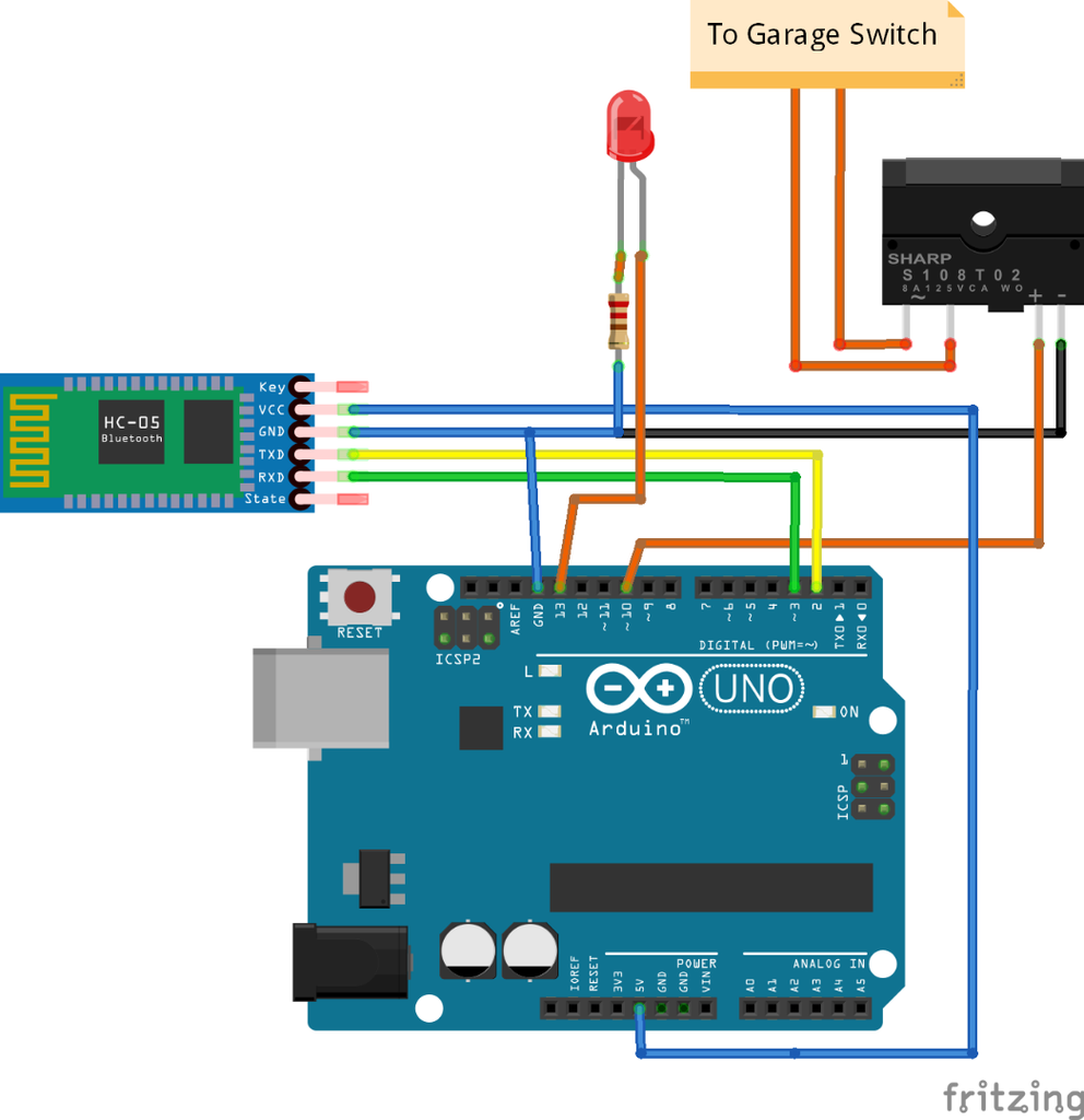


This is actually a very simple way to open your garage. You just need some kind of switch inside the garage where you can open the Garage with (I included a picture of an example). You need to connect the switch with an Relay or an Optokoppler to your Arduino. You can change the pin in the App, standard is pin 10. It turns the pin on for a few seconds and then turns it off again. That should open your Garage.
- Caution:
- This is not 100% save.
- This is NOT 100% save!!!
- THIS IS NOT 100% SAVE!!!!!
- I am not liable if someone gets unallowed Access to your home
- Someone could hack your Arduino and open your garage!!!
- You should NOT secure your FRONT DOOR with this.
- You should definitely change the "garageCode" Value inside the sketch.
Do NOT connect the Arduino DIRECTLY to the Garage Switch. It could damage your Arduino.
Don NOT use PIN 13 for the Relay/Optokoppler. Pin 13 often blinks when the Arduino is being resets. This could open your garage.
---
Ps.: This is not 100% save. I hope you got it :)
Step 12: Part 3: the Basic Bluetooth Connect App - the Robot Function


ROBOTS!!! Who doesn't like Robots? So here i will focus on two very simple ones. Both move around with two DC Motors. The first one(Mode: 1) has One motor on the left and one on the right wheel. The second(Mode: 2) has one on the rear axle that moves the robot forward and one on the front axle that decides in wich direction the robot moves. I use the motors with an l293d motor driver but any other compatible driver chip should work. But if your driver chip has no "Enable"-Pins or you just connected them to 5V then the "Move" and "Turn" functions will have the same effect if you use Mode 1. In Mode 2 you do not need the "Enable"-Pins. In both modes you need two "Input"-Pins per motor. If you want to know how to wore them, just look at the pictures.
Step 13: Part 3: the Basic Bluetooth Connect App - the AnalogRead Function

//ToDo
yeah..... welll.... still working on that...so... stay tuned i guess
Step 14: Part 4: Create You Own Stuff


Note: This is not yet the final version of the explanation and i will also update the "Your own Stuff" - Section inside the app.
When you select "Your own Stuff" under "Select Mode" inside the App you will see 10 Textboxes you can edit. When you press "Send" they will be send to your Arduino and parted again so you can use the individual data blocks. In the Arduino Sketch they are called "part1" till "part10". "part0" is predetermined to be "OWN" so the "OWN" void is being executed (pictures!). Here you can put in whatever you want. you can look into the built-in functions if you want to see some examples. It is actually very easy.
If this topic needs more explanation or you have some ideas how to improve the "Your own Stuff" - Section, please let me know.
Step 15: Part 5: Conclusion and to Do List

Sooo... yeah.. that's it I guess. If you have any Suggestion let me know. I still want to improve some Stuff, especially the speed of the transformation but i'm not sure if that's even possible :(
--
To Do List:
Version: 1.3.0
- improve the On/Off Section
- redesign the "Your own Stuff" Section
- create the AnalogRead Section
- implement a TinyDB so the App remembers your Changes (pins ,times, own Stuff, Bluetooth Module...)
- creating an update information as soon as there is a new version
Version: 1.3.1
- Robot: Maybe add an Mode 3 for Servos? (does anyone need that?)
---
Changelog
1.3.0:
- Created the Instructables
- Created the EBTC and BBTC Apps
- Created the UBTC and SoftwareSerialExampleUBTC Arduino Sketches
- Created the Pictures
1.3.1:
- Added the Robot and the Garage Section
- General improvements
- Updated Apps and Sketches
--
Solutions:
analogWrite(6,128);
digitalWrite(12,LOW);

Participated in the
Arduino All The Things! Contest


