

Introduction: Arduino VU Meter


Lets make a simple Arduino VU meter!!!
Step 1: Components


· LM386 operational amplifier
· Electret microphone condenser
· Arduino duemilanove
· 10k potentiometer
· Capacitors: 47 nF, 1uF, 10uF, 100uF, 100nF
· Resistors: 10Ω, 22k
· 6 LEDs
To distinguish between the electret positive and negative terminal, perform a continuity test. Measure the resistance between each pin/terminal and the outer casing of the electret. The resistance between the negative pin and the casing should be zero, since they are connected.
Also make sure you understand the LM386 pin configuration as shown in the diagram
Step 2: Electret Circuit


Connect the positive pin of the electret to a 22k resistor and then to the 5v of the arduino.
Connect a capacitor in parallel with the 22k resistor. The capacitor cathode should then connect to the amplifier circuit
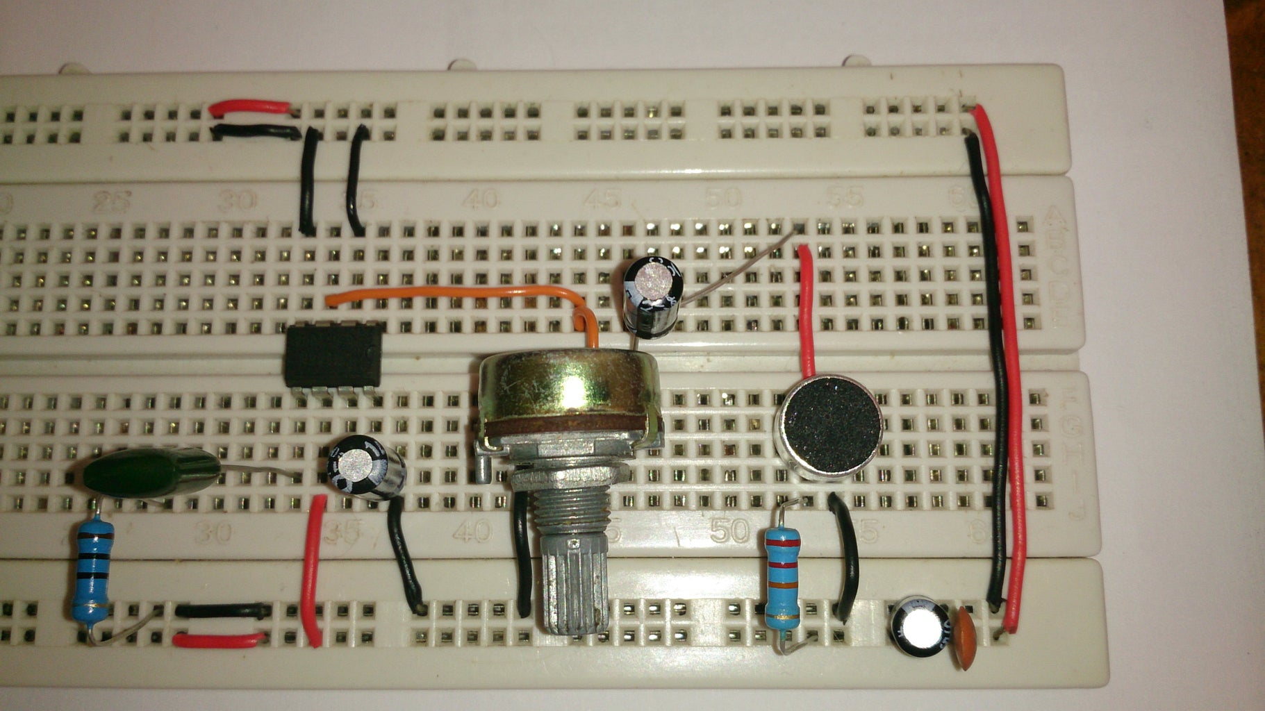
Step 3: Amplifier Circuit


The connection is done as shown above. That is why it is important for you to learn the LM386 pin numbers that i showed you in a previous image.
Pin 1 and 8 are not connected to anything, since i will be using the default gain (20x)
Pin 2 and 4 are connected to ground
Pin 3 is is the input and is connected to the input (10k potentiometer slider)
Pin 5 is the output. Its connected to a 47nF capacitor (current bank) and a 10 ohm pulldown resistor. The output is tapped from the pin before the current bank connection.
Pin 6 is connected to 5v
Pin 7 is connected to a 1uF cap and then to ground
Step 4: Video
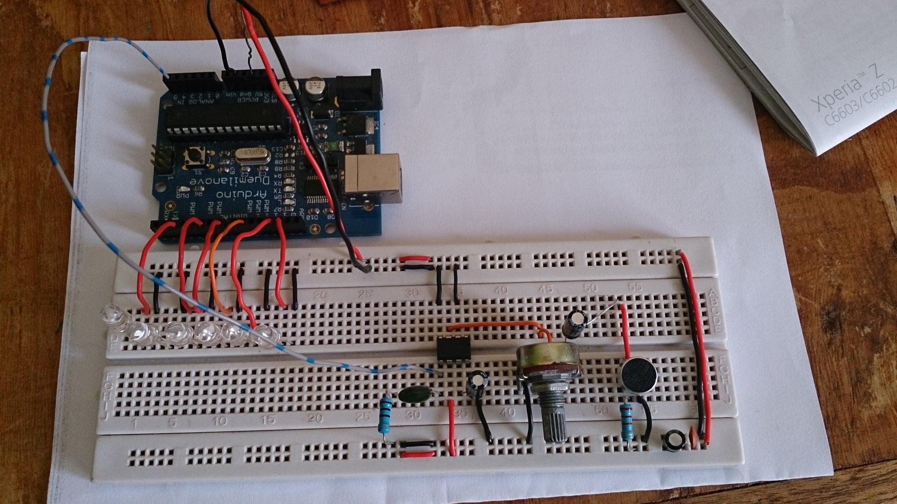
Step 5: Complete Setup


Here is the complete setup. Upload the code below and enjoy the show.
To learn more about the arduino VU meter and LM386+electret circuit, please visit the link below:
http://www.arduino-hacks.com/arduino-vu-meter-lm386electret-microphone-condenser/


