

Introduction: Arduino Volume Control


ArduinoUNO with volume control, pause/play button, and LCD display:
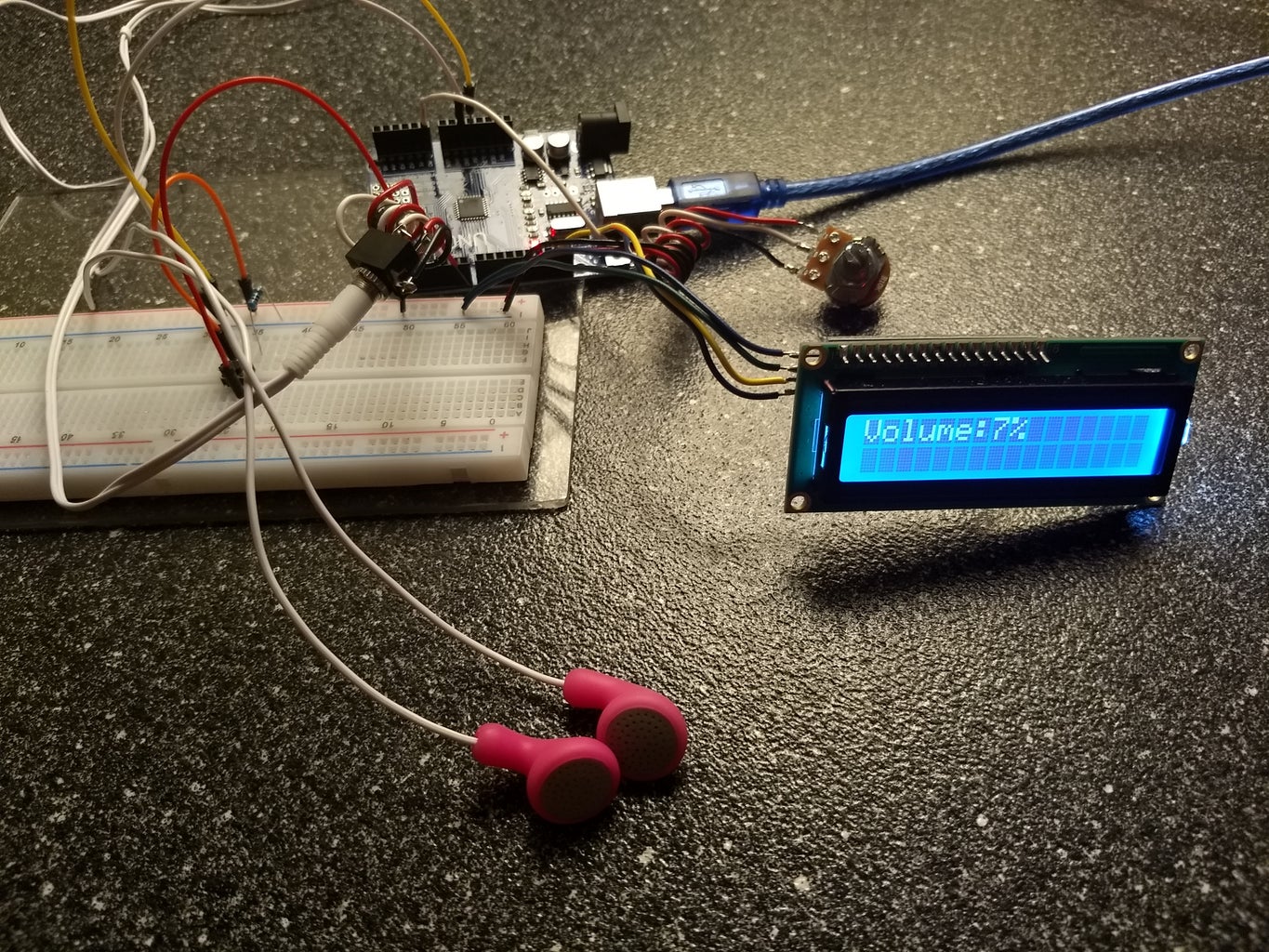
This tutorial will show you how to set up an arduinoUNO to produce a tone through standard earphones, with volume control via potentiometer, with visual volume display via LCD, with pause/play button.
Step 1: Pieces, Parts
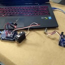
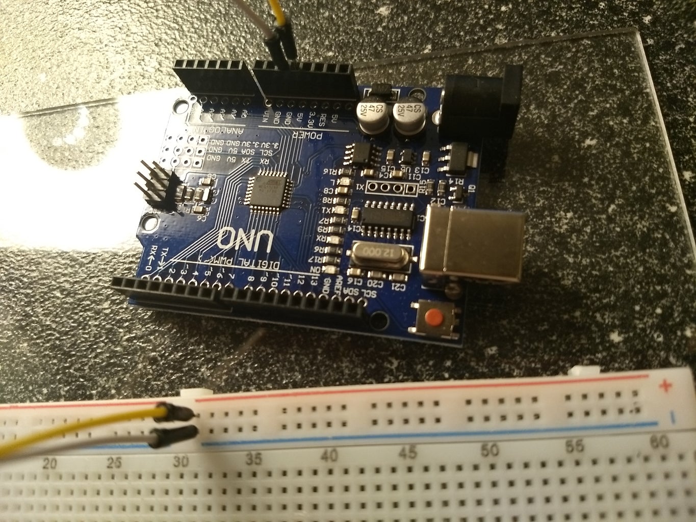
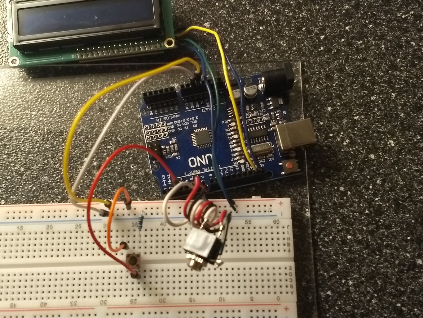
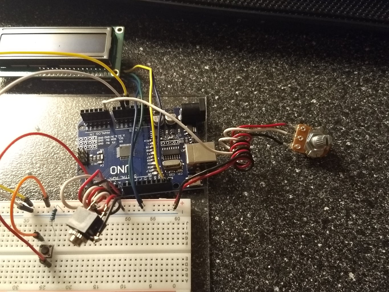
The image shows the components used in this demonstration.
-solderless breadboard (attached to acryllic base in photo)
-standard earphones
-analog potentiometer
-3.5mm jack
-16x2 LCD with I2c "backpack" chip
-button
-10 ohm resistor(shown above the button)
-arduinoUNO with USB connector
-solderless wires
Step 2: A Note About Soldering:
While designing this example, the solderless connections on these components were unreliable.
This demonstration does not include soldering, but it should be noted that connections have been soldered to this hardware.
-potentiometer
-3.5mm jack
-LCD
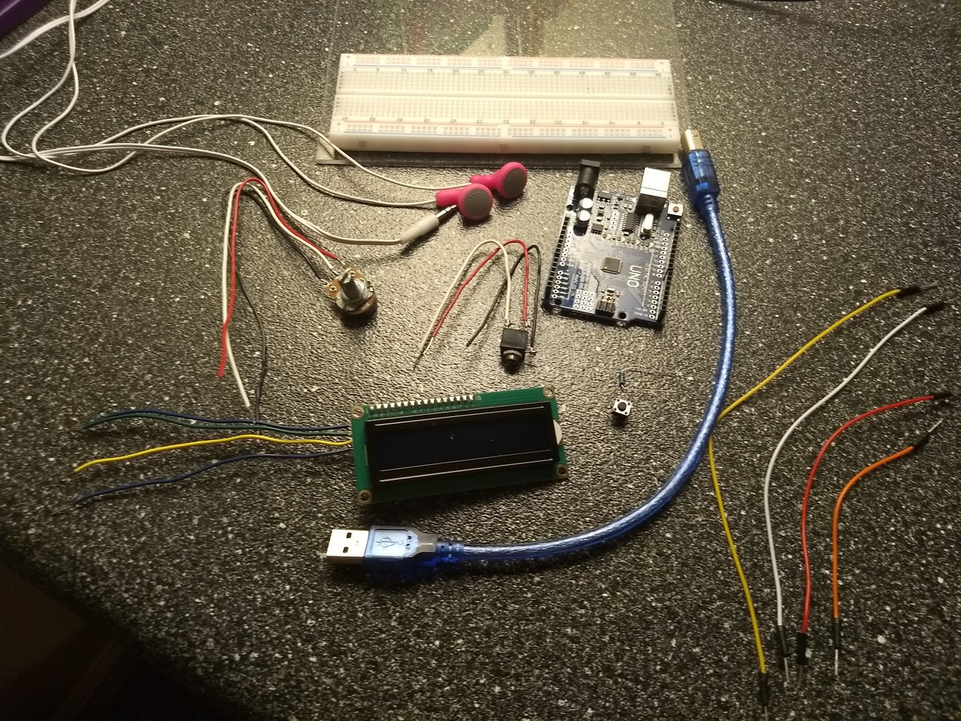
Also noteable in this image, the black I2c "backpack" chip is visible on the back of the LCD. Normally the LCD interfaces with 16 connections. One function of the I2c is to reduce this number to 4. This is where the soldered connections are made.
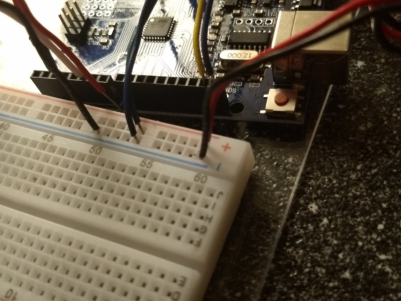
Step 3: Power and Ground:
Begin by attaching power and ground connections to the solderless breadboard with the solderless connector wires.
This makes supplying power to and grounding the rest of the circuit much more manageable since there are very limited pins on the arduino.
Step 4: Pause/Play Button:
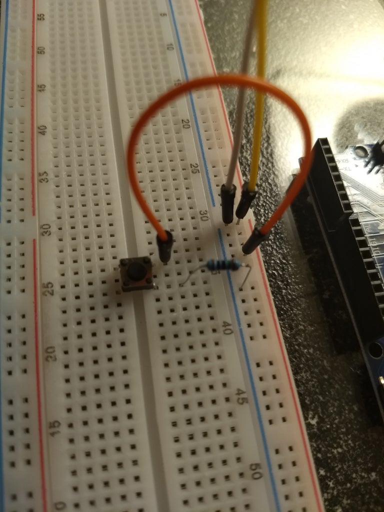
In the image, the button straddles the two halves of the breadboard. This is just to leave plenty of space.
The 10ohm resistor is connected to the ground rail and one side of the button.
Another solderless connector wire connects the other side of the button to the power rail.
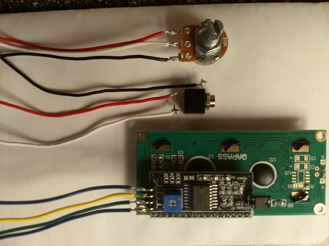
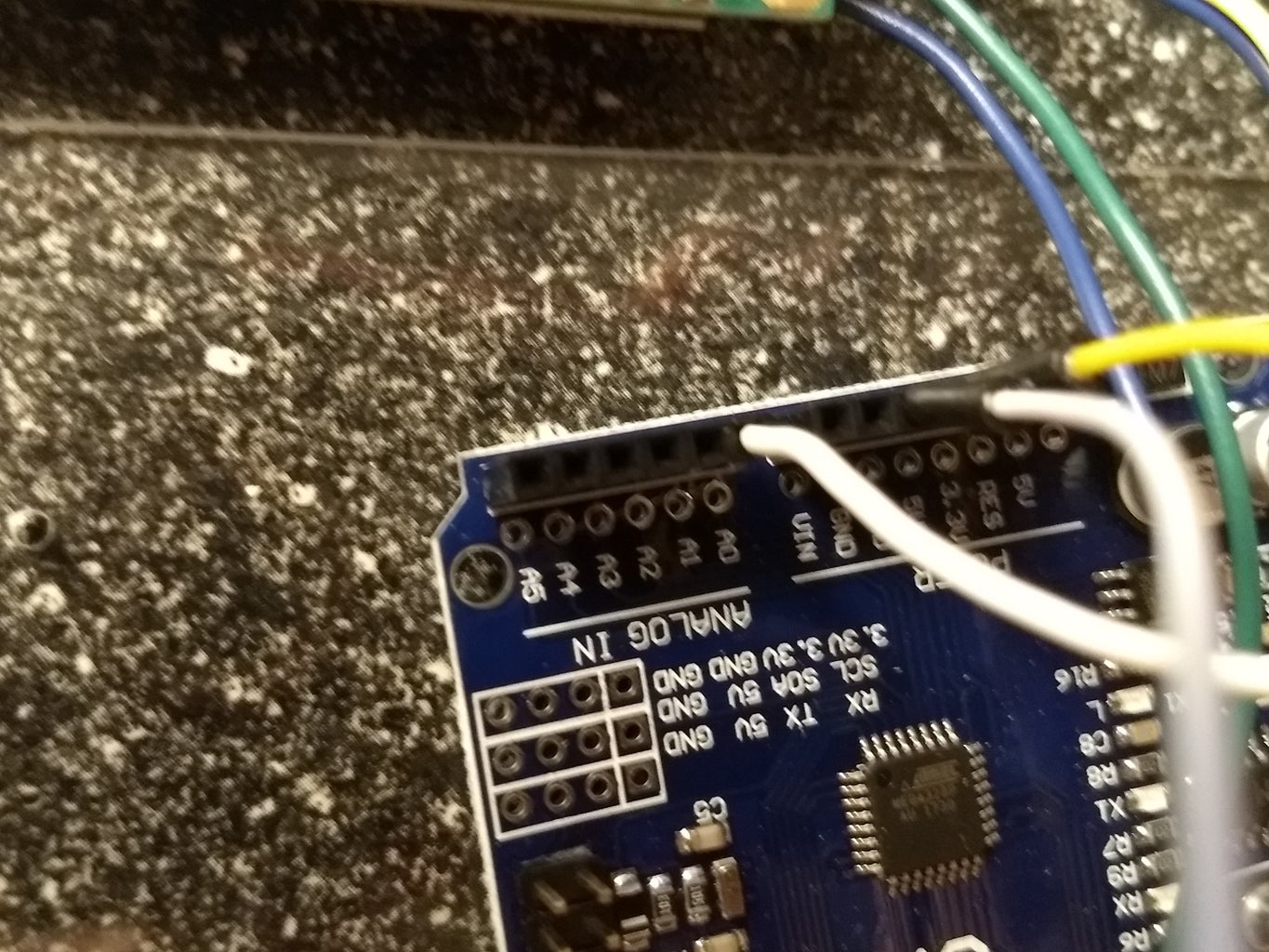
Step 5: Connect the LCD:
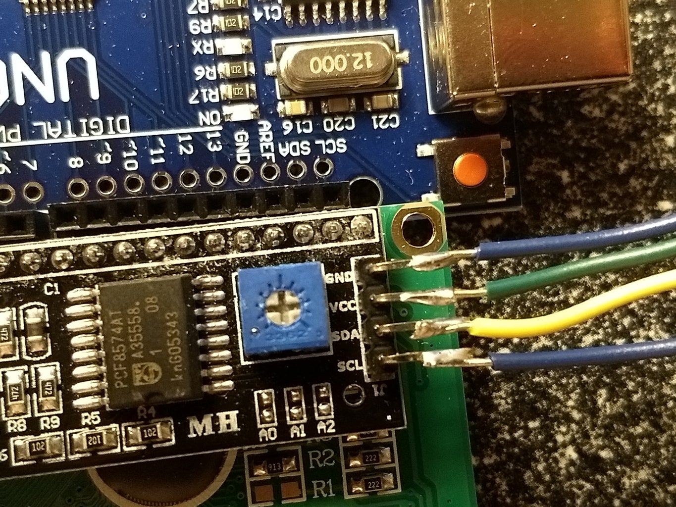

The Ic2 chip and the arduino are both labeled to help identify where connections belong.
SDA and SCL (blue and yellow) connect to the ardunio in the pins labeled the same.
GND and VCC are ground and 5v respectively. Connect them to the ground and power rails on the breadboard.
Step 6: Connect the 3.5mm Jack:
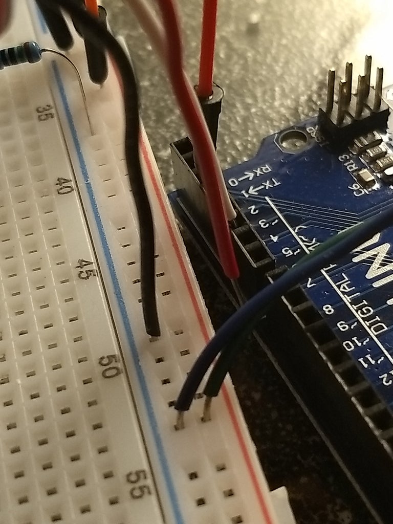
The component in the image has 3 leads: two channels (right and left), and ground. This demonstration only produces one channel of audio. It was unclear during my preparation whether arduino was capable of controlling two channels. Either way, the image shows one lead from the 3.5mm jack remains unconnected (red, in this case).
One feature of the volume control library utilized in this example, as well as the arduino hardware, is that pin5 must be used for the audio output.
The image shows the black ground wire from the 3.5mm jack connected to the ground rail of the breadboard and the white wire connected to pin5.
Step 7: Connect the Potentiometer:
The potentiometer also has three leads. The only difference between the outside pins is high and low. If you had two identical set-ups and switched the outside connections of the potentiometer, the only difference would be that you would have to turn the knob the opposite direction to increase or decrease volume.
That said, one outside pin connects the ground rail (black wire in image) on the bread board, and the other connects to the power rail (red wire in image).
The middle pin (white wire in image) connects to an ANALOG pin on the arduino, A0 in the image. These pins interpret analog input as opposed to digital signals like the rest of the arduino.
Step 8: Code:
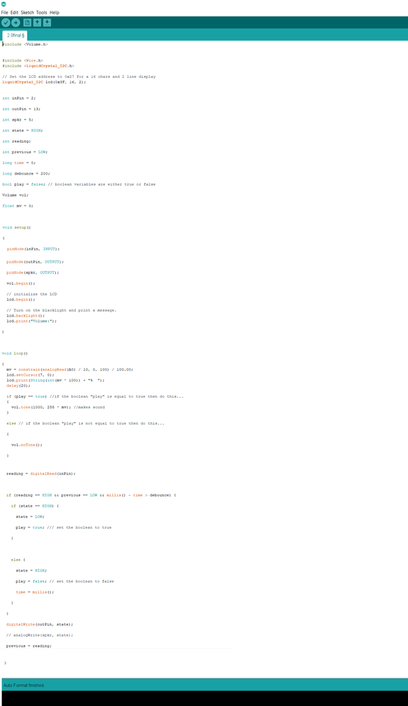
Unfortunately, I cannot comment much on the code. What is provided here was a collaborative effort involving a great deal of guidance. Many Bothans died to enable this code's success.
--------------------------------------------
#include <Volume.h>
#include <Wire.h>
#include <LiquidCrystal_I2C.h>
// Set the LCD address to 0x27 for a 16 chars and 2 line display
LiquidCrystal_I2C lcd(0x3F, 16, 2);
int inPin = 2;
int outPin = 13;
int spkr = 5;
int state = HIGH;
int reading;
int previous = LOW;
long time = 0;
long debounce = 200;
bool play = false; // boolean variables are either true or false
Volume vol;
float mv = 0;
void setup()
{
pinMode(inPin, INPUT);
pinMode(outPin, OUTPUT);
pinMode(spkr, OUTPUT);
vol.begin();
// initialize the LCD lcd.begin();
// Turn on the blacklight and print a message.
lcd.backlight();
lcd.print("Volume:");
}
void loop()
{
mv = constrain(analogRead(A0) / 10, 0, 100) / 100.00;
lcd.setCursor(7,0);
lcd.print(String(int(mv*100)) + "% ");
delay(20);
if (play == true) //if the boolean "play" is equal to true then do this...
{
vol.tone(1000, 255 * mv); //makes sound
}
else // if the boolean "play" is not equal to true then do this...
{
vol.noTone();
}
reading = digitalRead(inPin);
if (reading == HIGH && previous == LOW && millis() - time > debounce) {
if (state == HIGH) {
state = LOW;
play = true; /// set the boolean to true
}
else {
state = HIGH;
play = false; // set the boolean to false
time = millis();
}
}
digitalWrite(outPin, state);
// analogWrite(spkr, state);
previous = reading;
}
Step 9: Libraries:
This code utilizes certain libraries, or premade code. This demonstration does not address library installation (which is quite simple, just google it), but provided are links to the resources used in this example.
https://github.com/connornishijima/arduino-volume1... //volume library
https://playground.arduino.cc/Main/I2cScanner //i2c address finder
https://github.com/fdebrabander/Arduino-LiquidCry... //lcd+i2c library
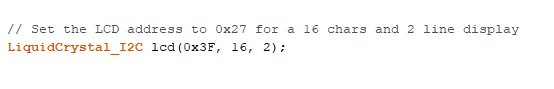
The LCD I2c has an address that is part of the code. The link above called "i2c address finder" is an arduino program which, while not used in the code like the other libraries, returns the address of the I2c in the SERIAL MONITOR.
The image shows the section of the code where the LCD address has to be input. In this case the address is 0x3F.
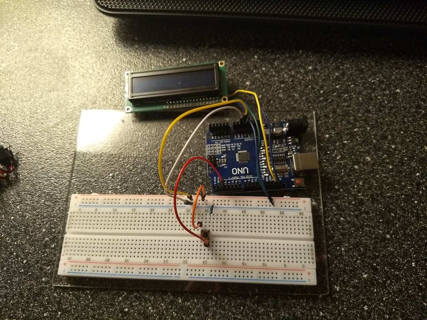
Step 10: Complete:

Attach the earphones in the 3.5mm jack in the usual way. Connect the arduino to a computer via the USB port. Using the arduino software, install the libraries and upload the code.
This example retains an element from an arduino example code that turns the onboard LED on and off. This was useful during the design process to provide feedback about the programs function when the other components did not do this. Isn't that fun?


