

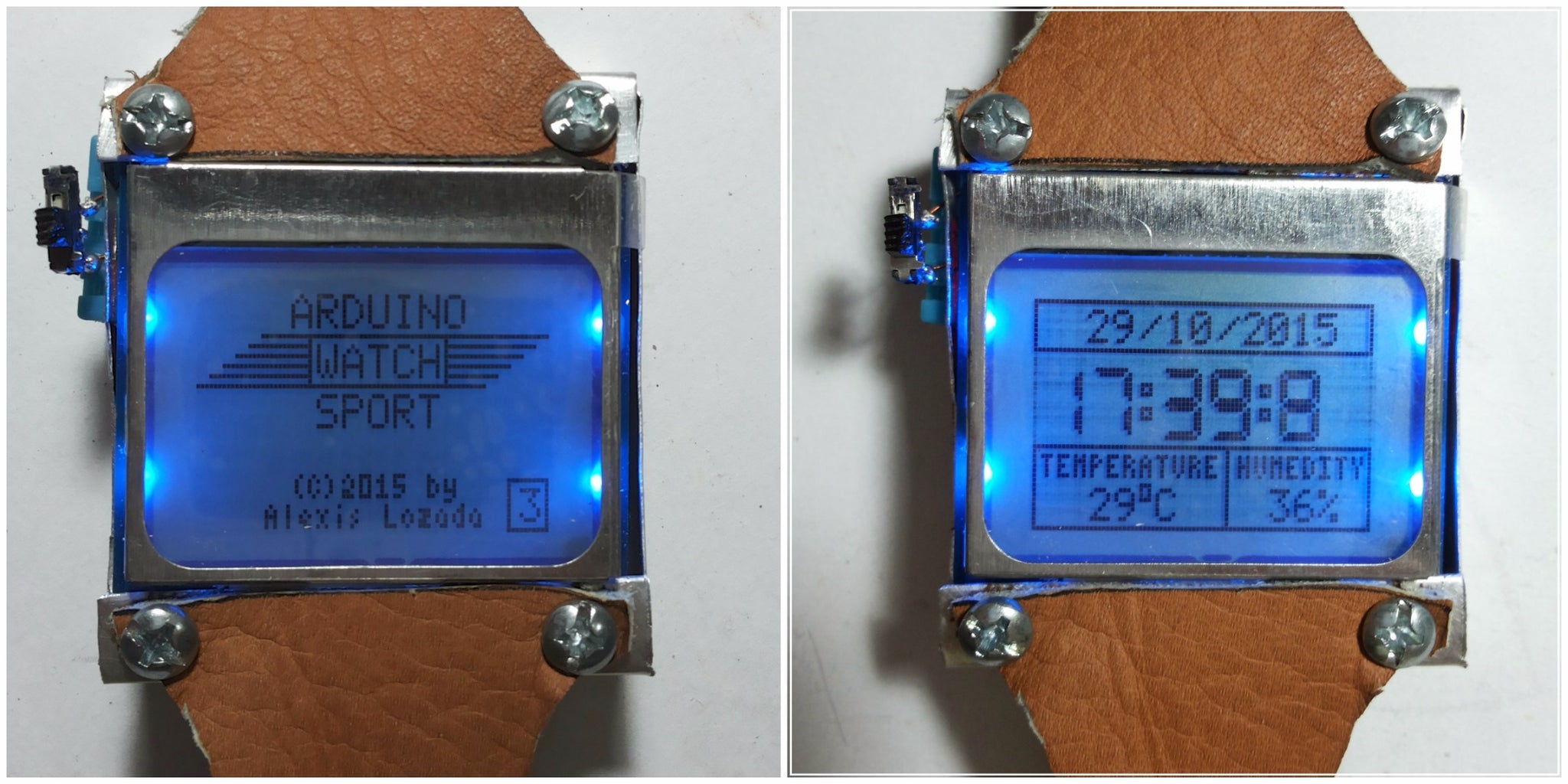
Introduction: Arduino Watch Sport


I apologize if you find spelling errors or nonsensical text, my language is Spanish and has not been easy to translate, I will improve my English to continue composing instructables.
In today's technology, especially electronics have come a long way, to the point that today can make projects a few years ago were very complicated to implement, thanks to these technological advances are now able to design and implement our houses projects.
and through this article I come to show you my new project, which consists of a wristwatch, so I called Arduino Watch Sport.
Step 1: Vídeo !
Step 2: Materials !

List:
- Sheet from Aluminum
- Battery 3.7V - 930mA
- Arduino Mini Pro 5V - 16MHz
- Converter RS232
- Module Clock RTC DS3231
- Wire from copper
- Module from Temperature - Humedity
- LCD Nokia 5110
- Leather 20X20cm
- Screws X4
- Switch
Step 3: Arduino Pro Mini

Overview
The Arduino Pro Mini is a microcontroller board based on the ATmega328 (datasheet). It has 14 digital input/output pins (of which 6 can be used as PWM outputs), 6 analog inputs, an on-board resonator, a reset button, and holes for mounting pin headers. A six pin header can be connected to an FTDI cable or Sparkfun breakout board to provide USB power and communication to the board.
The Arduino Pro Mini is intended for semi-permanent installation in objects or exhibitions. The board comes without pre-mounted headers, allowing the use of various types of connectors or direct soldering of wires. The pin layout is compatible with the Arduino Mini. There are two version of the Pro Mini.
One runs at 3.3V and 8 MHz, the other at 5V and 16 MHz.
Summary
Microcontroller...................ATmega328
Operating Voltage.............3.3V or 5V (depending on model)
Input Voltage.....................3.35 -12 V (3.3V model) or 5 - 12 V (5V model)
Digital I/O Pins..................14 (of which 6 provide PWM output)
Analog Input Pins..............6
DC Current per I/O............Pin 40 mA
Flash Memory....................32 kB (of which 0.5 kB used by bootloader)
SRAM ................................2 kB
EEPROM...........................1 kB
Clock Speed.......................8 MHz (3.3V model) or 16 MHz (5V model)
Input and Output
Each of the 14 digital pins on the Pro Mini can be used as an input or output, using pinMode(), digitalWrite(), anddigitalRead() functions. They operate at 3.3 or 5 volts (depending on the model). Each pin can provide or receive a maximum of 40 mA and has an internal pull-up resistor (disconnected by default) of 20-50 kOhms. In addition, some pins have specialized functions:
- Serial: 0 (RX) and 1 (TX). Used to receive (RX) and transmit (TX) TTL serial data. These pins are connected to the TX-0 and RX-1 pins of the six pin header.
- External Interrupts: 2 and 3. These pins can be configured to trigger an interrupt on a low value, a rising or falling edge, or a change in value. See the attachInterrupt() function for details.
- PWM: 3, 5, 6, 9, 10, and 11. Provide 8-bit PWM output with the analogWrite() function.
- SPI: 10 (SS), 11 (MOSI), 12 (MISO), 13 (SCK). These pins support SPI communication, which, although provided by the underlying hardware, is not currently included in the Arduino language.
- LED: 13. There is a built-in LED connected to digital pin 13. When the pin is HIGH value, the LED is on, when the pin is LOW, it's off.
The Pro Mini has 8 analog inputs, each of which provide 10 bits of resolution (i.e. 1024 different values). Four of them are on the headers on the edge of the board; two (inputs 4 and 5) on holes in the interior of the board. The analog inputs measure from ground to VCC. Additionally, some pins have specialized functionality: I2C: A4 (SDA) and A5 (SCL). Support I2C (TWI) communication using the Wire library.There is another pin on the board: Reset. Bring this line LOW to reset the microcontroller. Typically used to add a reset button to shields which block the one on the board.
- I2C: A4 (SDA) and A5 (SCL). Support I2C (TWI) communication using the Wire library.There is another pin on the board:
- Reset. Bring this line LOW to reset the microcontroller. Typically used to add a reset button to shields which block the one on the board.
Step 4: Arduino Pro Mini + Serial Adapter RS232

In this guide I'll show you how to connect the Converter RS232 to the Arduino Mini Pro
We use the Converter RS232. So connecting it to an Arduino Mini Pro 3.3V Atmega328 can be confusing.
- Connect USB 3.3V to Arduino VCC. (red)
- Connect USB Ground to Arduino BLK. (black)
- Connect USB TXO to Arduino RXI. (yellow)
- Connect USB RXD to Arduino TXD. (blue)
- Connect DTR (Data terminal Ready, which is basically a RS-232 line) to Arduino GRN. (green)
Step 5: LCD Nokia 5110

Overview
This is a quick tutorial for our 84x48 pixel monochrome LCD display. These displays are small, only
about 1.5" diameter, but very readable due and comes with a backlight. This display is made of 84x48 individual pixels, so you can use it for graphics, text or bitmaps. These displays are inexpensive, easy to use, require only a few digital I/O pins and are fairly low power as well.
To drive the display, you will need 3 to 5 digital output pins (depending on whether you want to manually control the chip select and reset lines). Another pin can be used to control (via on/off or PWM) the backlight. To make things easy for you, we've written a nice graphics library that can print text, pixels, rectangles, circles and lines! The library is written for the Arduino but can easily be ported to your favorite microcontroller
Power Requirements
The display uses the PCD8544 controller chip from Philips and were used in Nokia 3310 and 5110 cell phones. This chip is designed to run only at 3.3V and have 3v communication levels, so for 5V microcontrollers a logic level shifter is required (otherwise you could easily damage the display).
Connect:
SCK or CLK...........Pin 8 arduino
MOSI or DIN..........Pin 9 arduino
DC..........................Pin 10 arduino
RST........................Pin 11 arduino
CS or CE................Pin 12 arduino
VCC........................3.3V arduino
BL...........................5V Arduino
GND.......................Ground of arduino
LIBRARY:
It includes: Guide + Example + Library
Attachments

Step 6: Module Clock RTC DS3231

DS3231
The DS3231 module allow that we can keep records detailed the passage of time in our microcontroller.The proyect we can carry out this module ranging from sensor stations to alarms and data logging probes.
On many occasions we will need our projects to keep a strict count of the elapsed time. This is impossible to achieve with our Arduino because it is not qualified to do so. We need a circuit that is capable of maintaining the time counting even when the microcontroller is off.
Fortunately is the DS3231 module.
This module includes an integrated circuit, the DS3231, and a voltage regulator, 3.6V battery (of those found in computer motherboard), inter alia (is able to measure temperature).
It communicates with Arduino using the I2C protocol, so find the VCC, GND, SCL and SDA pins.
Once you have downloaded and installed the library we can proceed to use our module. As always, every time you go to use the I2C interface pin A4 and A5 should be reserved for connecting the SDA and SCL respectively.
Arduino connections must be made as follows.
Connect:
Pin DS3231...................PIN ARDUINO
SCL................................A5
SDA................................A4
VCC...............................3.3V
GND...............................GND
32K.................................DO NOT CONNECT
SQW...............................DO NOT CONNECT
LIBRARY:
Attachments
Step 7: SENSOR DHT11

DHT11
These sensors are very basic and slow, but are great for hobbyists who want to do some basic data logging. The DHT sensors are made of two parts, a capacitive humidity sensor and a thermistor. There is also a very basic chip inside that does some analog to digital conversion and spits out a digital signal with the temperature and humidity. The digital signal is fairly easy to read using any microcontroller.
Characteristics:
- Ultra low cost
- 3 to 5V power and I/O
- 2.5mA max current use during conversion (while requesting data)
- Good for 20-80% humidity readings with 5% accuracy
- Good for 0-50°C temperature readings ±2°C accuracy
- No more than 1 Hz sampling rate (once every second)
- Body size 15.5mm x 12mm x 5.5mm
- 4 pins with 0.1" spacing
LIBRARY:
Attachments
Step 8: We Connect the Battery !

Step 9: We Connect the LCD Nokia 5110 !

Step 10: We Connect the Sensor DHT11 !

Step 11: We Connect the Module Clock RTC DS3231 !

Step 12: Cutting Sheet From Aluminum!

Step 13: Protection of Circuit !

I have taken into account some comments made me whether aluminum is conductive or not, it's actually very conductive and always have been considered, only I had no problems in the case of my watch, but the comments are very successful and caution should I protect the circuit.
For this reason I take the time to isolate the aluminum box with cardboard, keep in mind that the copper wire is insulated with a coating, which makes the copper wire in its non-conducting surface.
Gracias por los comentarios!
Step 14: Fitting Parts !

Step 15: Bracelet in Leather !

Step 16: Together !

Step 17: END !
Annex code used in this project, do not forget to download each of the libraries for the proper functioning of the same.
Thank you !
Attachments

Second Prize in the
Wearable Tech Contest

First Prize in the
Epilog Contest VII
Second Prize in the
Time Contest


