

Introduction: Arduino WiFi Thermometer (with Web Page) - Arduino Wireless


What you need
- An Arduino board (any compatible board is OK).
- LM-35 (to use with the provided file you can use DS18B20 but you have to convert the source code respectively).
- HLK-RM04 WiFi router module.
- 5V Power supply or Power supply and regulation circuit.
Step 1: The Idea
Arduino can be easily turned into a thermometer just by using the LM-35 sensor (or any other temperature sensor). There are a ton of examples on the internet about it.
The problem is that in order to read the environment temperature you have to connect the device to the computer using USB connection you have to use an Ethernet shield or a WiFi shield in order to connect the device to TCP/IP Network.
My approach is much cheaper since you can connect any Arduino compatible device even the ones without the USB connection circuit (boards like Arduino Pro Mini) to the TCP/IP network using wireless connection.
TIP: You can create your own Arduino compatible board by using just an ATMEGA328 μP unit and some peripheral parts or you can use Arduino compatible devices like the Redesign Pro Mini atmega328 5V which can be found on ebay.com for about 2,00 €.
The idea of wireless temperature meter can be improved and converted into a complete weather station or it can be used as a low cost WiFi interface to control various devices around your house just by powering up the Arduino based device.
Step 2: The Result


You can get a self-refreshing web page which looks like this (or even better if you tweak the html code).
TIP: HTML is cool. You can access this page from everywhere. You just have to forward one TCP port to your router and the page can be accessed via the internet. So why not access the page just by using you smartphone?
Step 3: The Hardware

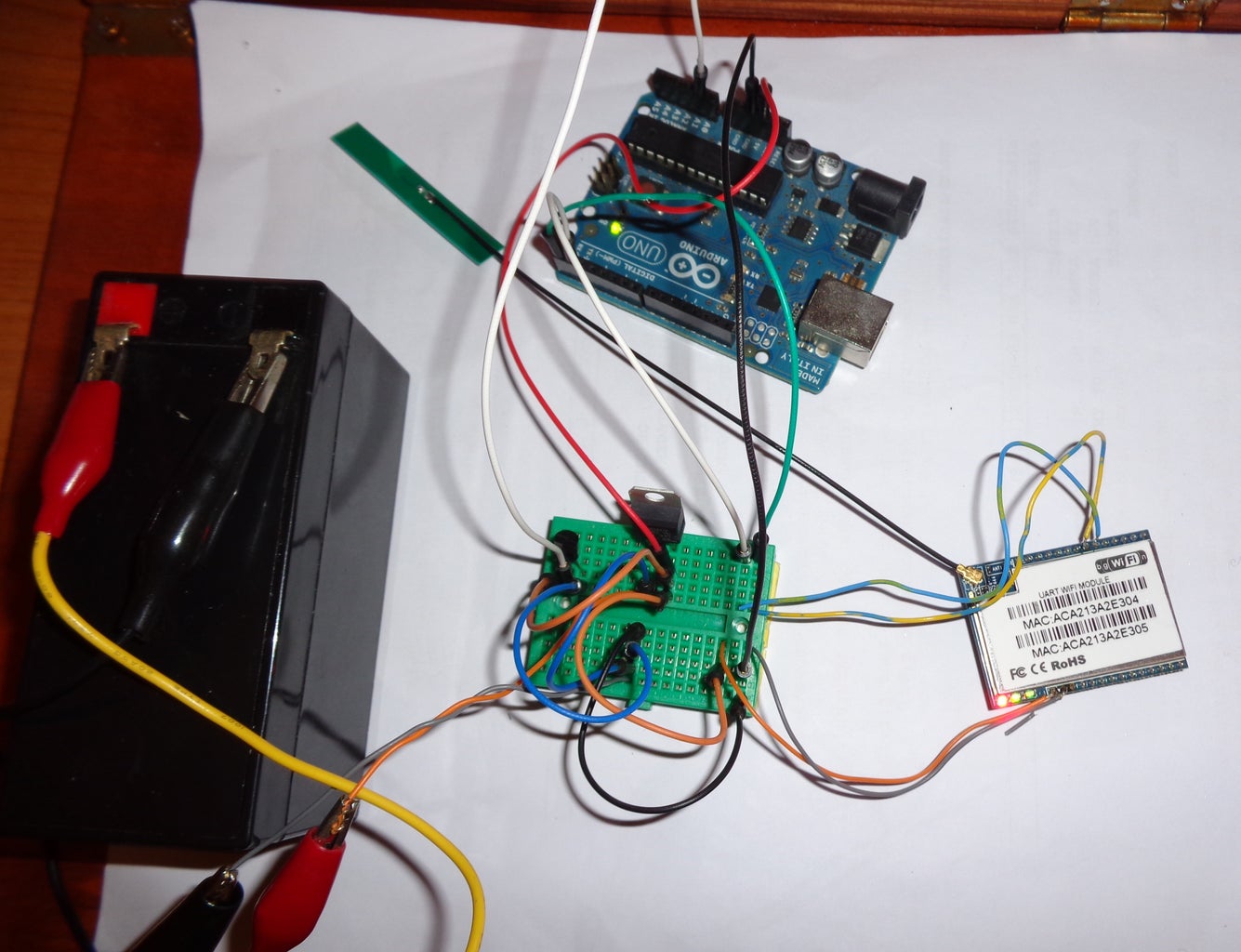
The connections can be found on the provided diagram. It is assumed that we are using a 12V DC power supply (which is the most common case). The input power is regulated by the 7805 5V DC regulator in order to supply both Arduino and HLK-RM04 WiFi module.
The output from 7805 is connected to 5V Arduino board and pin 1 on the WiFi module. Of course the grounds are connected together.
The Arduino pins 0 and 1 are connected to wireless modules pins 21 and 20 by crossing the RX and TX signals. Pin 1 of Arduino is connected to Pin 21 of HLK-RM04 and Pin 0 is connected to Pin 20.
The temperature sensor provides output on the center pin, so this pin goes to the A1 (Analog pin) on the Arduino board left pin is connected to 5V and right pin to GND (please check the diagram to identify pins).
Step 4: The Wireless Module Configuration

When it is powered with the default configuration the HLK-RM04 WiFi module acts as a wireless access point which can help in order to configure it properly for our application.
Configuration procedure:
By using the wireless network discovery from a PC or tablet or even a smartphone we are looking or a SSID named HI_LINK_xxxx (e.g. HI_LINK_4EBB).
We are connecting our device to this wireless network by using the password: 12345678
Once we are connected to the network and our device has obtained an IP address from its DHCP we are opening the configuration page of the module by typing the following IP address to a new browser window 192.168.16.254
The username is admin and the password is admin as well.
On the configuration you should be automatically see the HLK-RM04 Serial2Net setting page.
You have to change the settings on this page in order to connect this device to your wireless network.
Finally set the serial baud rate to 57600 and the network timeout to 10 seconds.
Check the following video to see all the steps:
Step 5: The Firmware (The Arduino Sketch)
The Arduino sketch is mainly based on the work provided by http://rayshobby.net/?p=9592
The provided code can be improved to format the output page as you like (although HTML formating is a bit of pain to converted to code).
Attachments

Step 6: About HLK-RM04

The HLK-RM04 is a low cost wired / wireless router with serial ports. You can find more info about it here: http://www.hlktech.net/product_detail.php?ProId=39
You can buy themodule from ebay for around 10,00 € http://www.ebay.com/sch/i.html?_from=R40&_trksid=p... . However be careful when you are selecting the device since most of the times it is provided without the antenna pigtail. So when you are bidding please check if the antenna is included.
There is also a version with ceramic antenna fitted on board which is not requires any other antenna component.
Finally be noticed that the module's pinout is 2mm which can not fit on standard breadboards.


