

Introduction: CubeSat Accelerometer Tutorial


A cubesat is a type of of miniaturized satellite for space research that is made up of multiples of 10x10x10 cm cubic units and a mass of no more than 1.33 kilograms per unit. Cubesats enable a great quantity of satellites to be sent to space and allow the owner complete control over the machine no matter where on earth they are. Cubesats are also more affordable than any other current prototypes. Ultimately, cubesats facilitate immersion into space and spread knowledge of what our planet and universe looks like.
An Arduino is a platform, or computer of sorts, used for building electronics projects. An Arduino consists of both a programmable circuit board and a piece of software, that runs on your computer, used to write and upload computer code to the board.
For this project, our team was allowed to pick any sensor we wanted to detect any certain aspect of the makeup of Mars. We decided to go with an accelerometer, or an electromechanical device used to measure acceleration forces.
To make all these devices work together, we had to attach the accelerometer to the breadboard of the Arduino, and attach both to the inside of the cubesat, and make sure it withstood a flight simulation and a shake test. This instructable will cover how we accomplished this and the data we collected from the Arduino.
Step 1: Establish Goals(Alex)

Our main goal for this project, was to use an accelerometer (don't worry we'll explain what this is later) placed within a CubeSat, to measure the acceleration due to gravity on Mars. We were to build a CubeSat, and test it's durability in a variety of ways. The hardest part of goal setting and planning, was realizing how to contain the Arduino and the accelerometer within the CubeSat, in a safe way. To do this, we had to come up with a good CubeSat design, make sure it was 10x10x10cm, and make sure it weighed less than 1.3 kilograms.
We determined that Legos, would in fact prove durable, and also easy to build with. Legos were also something somebody could already have, rather than us spending money on any building materials. Fortunately, the process of coming up with a design did not take very long, as you will see in the next step.
Step 2: Design Cubesat

For this specific cubesat, we used legos for their ease to build, attachment, and durability. The cube sat must be 10x10x10 cm and weigh less than 1.33 kg (3 lbs) per U. The Legos make it easy to have an exact 10x10x10 cm while using two Lego bases for the floor and lid of the cubesat. You may have to saw down the Lego bases to get them exactly how you want them. Inside the cubesat, you will have your arduino, breadboard, battery, and SD card holder all attached to the walls using any adhesive you'd like. We used duct tape to ensure no pieces would become loose inside. To attach the cubesat to the orbiter we used string, rubber bands, and a zip tie. The rubber bands must be wrapped around the cubesat as if ribbon wrapped around a present. The string is then tied to the center of the rubberband on the lid. Then the string is looped through a zip tie that is then hooked to the orbiter.
Step 3: Construct Arduino


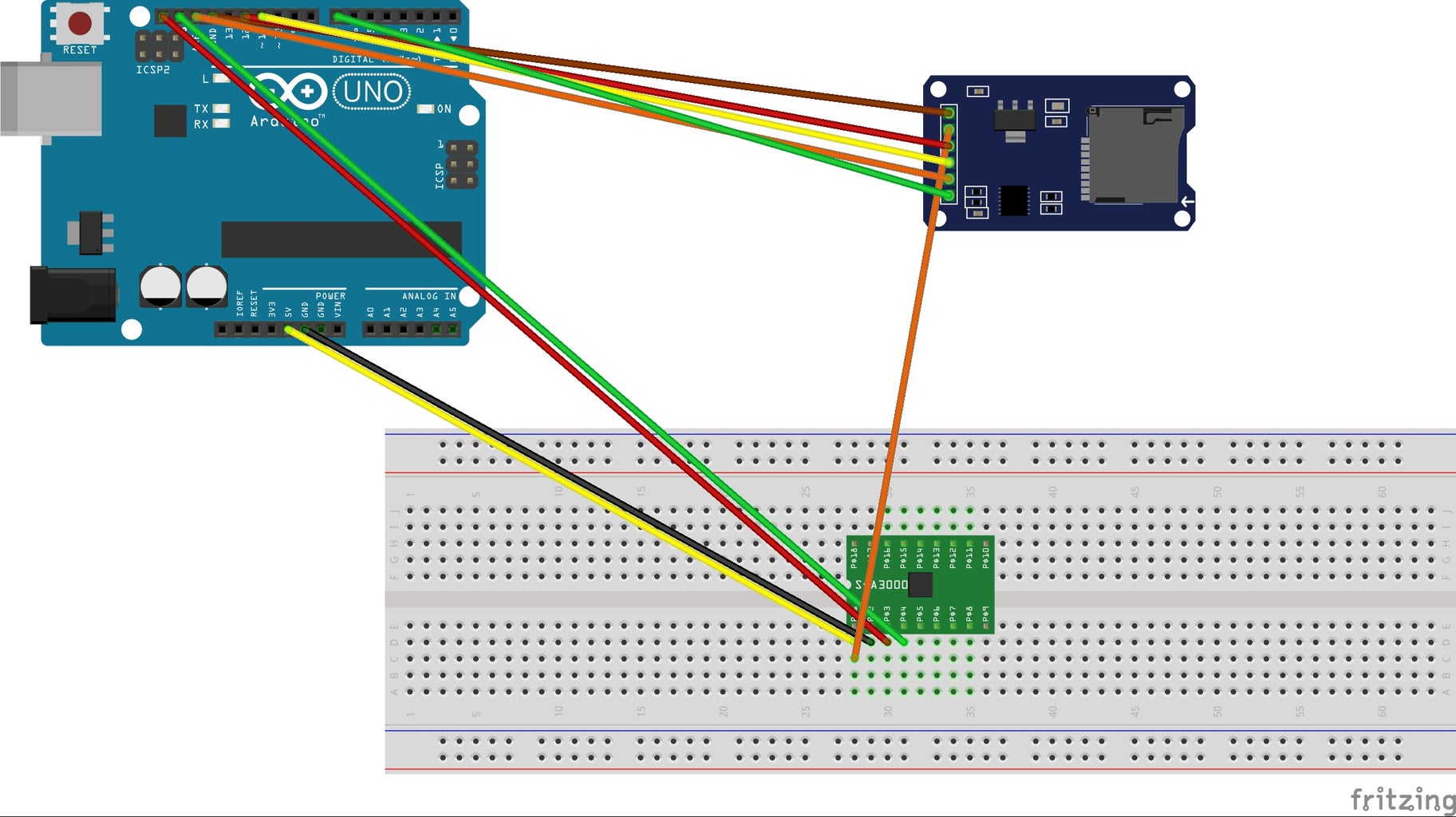
Our goal for this CubeSat, like said before, was to determine the acceleration due to gravity on Mars with an accelerometer. Accelerometers are integrated circuits or modules used to measure the acceleration of an object to which they are attached. In this project I learned the basics of coding and wiring. I used a mpu 6050 which is used as an electromechanical device that will measure acceleration forces. By sensing the amount of dynamic acceleration, you can analyze the way the device is moving on the X, Y, and Z axis. In other words, you can tell if it's moving up and down or side to side;an accelerometer and some code can easily give you the data to determine that information. The more sensitive the sensor, the more accurate and detailed the data will be. This means that for a given change in acceleration, there will be a larger change in signal.
I had to wire the arduino, which was already wired to the accelerometer, to the SD card holder which would store the data received during the flight test so we could then upload it to a computer. This way we can view the measurements of the X, Y, and Z axis to see where the cubesat was in the air. ou can view in the pictures attached how to wire the arduino to the accelerometer and breadboard.
Step 4: Flying and Vibration Tests(Alex)
In order to ensure cube sat durability, we had to put it through a series of tests, that would simulate the environment that it would be put through, in space.The first test we had to put the cube sat through was called the fly test. We had to string up the arduino to a device called an orbiter, and simulate it's flight path around the red planet. We tried multiple methods of attaching the cube sat, but eventually we were able to settle on a double rubber band that was wrapped around the cube sat. A string was then attached to the rubber bands.
The flight test was not immediately a success, as on our first try, some of the tape began to come off. We then switched designs to the rubber band option mentioned in the previous paragraph. Although on our second attempt, we were able to have the cub sat fly at the required speed, for 30 seconds, without any problems occurring at all.
The next test was the vibration test, which would loosely simulate the cube sat traveling through a planet's atmosphere. We had to put the cube sat on the vibration table and turn up the power to a certain degree. The cube sat then had to remain in tact for at least 30 seconds at this power level. Luckily for us, we were able to pass all aspects of the test on our first try. Now all that remained was the final data collecting and tests.
Step 5: Interpreting Data

With the data we got after doing out final test, you can see where the cube traveled on the X, Y, and Z axis and determine the acceleration by dividing your displacement by the time. This gives you the average velocity. Now, as long as the object is uniformly accelerating, you merely need to multiply the average velocity by 2 to get the final velocity. To find the acceleration, you take final velocity and divide it by the time.
Step 6: Conclusion


The ultimate goal of our project was to determine the acceleration of gravity around Mars. Through the data collected using the Arduino, it can be determined that the gravitational acceleration while orbiting Mars remains constant. Additionally, while traveling around Mars, the direction of orbit is constantly changing.
Overall, our team's biggest takeaways were our growth in our fluency in reading and writing code, our understanding of a new technology on the cutting edge of space exploration, and our familiarity with the inner workings and many uses of an Arduino.
Secondarily, throughout the project, our team not only learned the aforementioned technology and physics concepts, but we also learned project management skills. Some of these skills include meeting deadlines, adjusting for design oversights and unforeseen problems, and conducting daily standup meetings to give our group accountability and, in turn, keep everyone on track to meet our goals.
In conclusion, our team met every testing and data requirement, as well as learning invaluable physics and team management skills that we can carry into future efforts in school and in any groupwork-oriented profession.


